

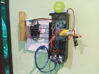
This is portable smart switch controller which, as it’s name suggests, is a portable device which can be attached on a switch board of any room. It allows using the appliances working on the switches, remotely using three different modes – “OK Google” voice command, Android app and Hand gesture. Device carries a lot more features like providing the electricity bill of the appliances it controls, finding anomaly in light schedule in room and also switch off the appliances after 3 hours of continuous usage.
Things used in this project
Hardware components -
- Bolt WiFi module
- Arduino Uno
- l293d Motor Driver
- Breadboard
- Ultrasonic sensor HC-SR04
- LED
- Temperature Sensor LM35
- Resistor 10k ohm
- 9V battery
- Servo Motor
- Jumper wires
- DC Motor, 12 V
- Light Dependent Resistor ( LDR )
Software components -
Hand tools and fabrication machine -
- Soldering iron
- Hot glue gun
Story
When it comes to home automation or using the home appliances remotely, the traditional method followed is using the relay module inside the switchboard to remotely control the appliances. This relay module will always remain with the connection of that appliance and for every appliance we have to use a different relay module. So, I came up with this idea of making a portable remote switch controller, which controls the appliances by toggling on and off the switches on the switchboard remotely. As seen in my demonstration video, The Servo Motor runs over the switches of the switchboard using a bolted power transmission mechanism thus having a control over all the switches which can be controlled remotely using three different methods that is, Hand Gesture, OK Google voice command and Android app remote control. The android app also allows getting the electricity bill of the appliances used. The anomaly detection algorithm detects if the lights were turned On at an unexpected time
Hardware Setup
Step 1: Hardware connections
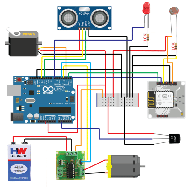
The connections are as follows:
Arduino pin 2 —> Input pin Servo.
pin 3, 4 –> Input 1, 2 of L293D motor driver.
pin 7 —> LED
pin 11 —> Echo pin Ultrasonic sensor
pin 12 —> Trig pin Ultrasonic sensor
pin A1 —> Output pin of LM35 temperature sensor
pin TX —> pin RX of BOLT wifi module
pin RX —> pin TX of BOLT wifi module
pin 3v3, A0 of BOLT wifi module —> LDR
Give 3.3v, 5v and Gnd for necessary components as shown in schematic diagram.
Software Programming
Step 1: Getting the Bolt API Key and Device ID
Login to cloud.boltiot.com and note the ID of your Bolt WiFi Module.
Now click on the API Tab and under the section for Generate Key, click on Enable.
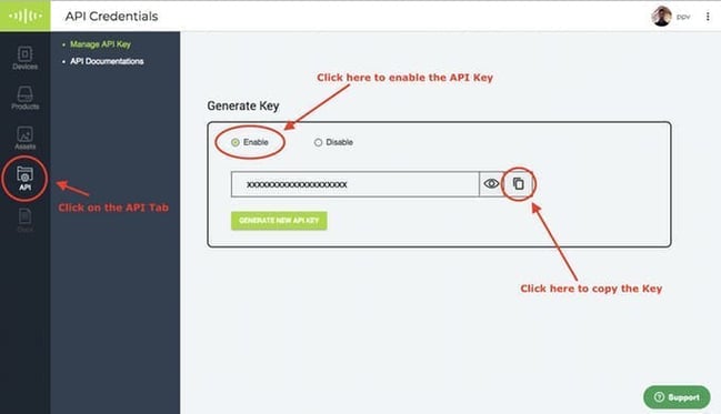
Next click on the copy button to copy your API key. Your API key will may look something like this: f1f918e9-d9c2-4e5b-aed0-b7cb743f74cf
Step 2: Creating the UART Control Command
Since we are using Arduino Uno in this project to perform the functions, we need to send a string to the Arduino board from Bolt Wifi module. This can be done by using serial Write command under UART commands.
Click here Bolt Cloud go to Docs Tab -> API Documentation -> UART Commands API -> Send Serial Data Output, to understand how to create a API command link to send a string to Bolt.
The structure of the command is:
https://cloud.boltiot.com/remote/API_KEY/serialWrite?data=STRING&deviceName=DEVICE_ID
The parameters that you need to replace are:
API_KEY: You can get it from API tab on cloud dashboard.
STRING: This is the string that we will send to Arduino through Bolt. We will decide which strings to send, later while writing the code for Arduino.
DEVICE_ID: The id of your device. You can get it from cloud dashboard.
The sample command to send a string “f” over the TX line of device having ID BOLT13819450 is:
https://cloud.boltiot.com/remote/f1f918e9-d9c2-4e5b-aed0-b7cb743f74cf/serialWrite?data=f&deviceName=BOLT13819450
We will also need to receive strings from Arduino for displaying bill of usage. This can be done using serial Read command under UART commands.
Click here Bolt Cloud go to Docs Tab -> API Documentation -> UART Commands API -> Read Serial Data Incoming, to understand how to create a API command link to receive a string to Bolt.
The structure of the command is:
https://cloud.boltiot.com/remote/API_KEY/serialRead?till=10&deviceName=DEVICE_ID
The sample command to read a string over the RX line of device having ID BOLT13819450 is:
https://cloud.boltiot.com/remote/f1f918e9-d9c2-4e5b-aed0-b7cb743f74cf/serialRead?till=10&deviceName=BOLT13819450
Make sure that you change the API Key to your own API Key and device ID which you got in the previous step.
Since we will use three methods i.e Google assistant, Android app and Hand gesture for controlling the switches let us see how to setup each method.
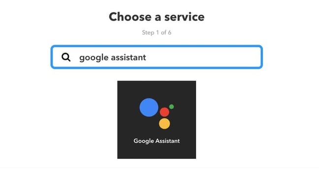
Step 3: IFTTT integration via Google Assistant and Webhooks
Go to IFTTT to create a new applet by clicking here
Login using your Gmail account. Make sure you use same account which you’ll be using on your mobile to interact with Google Assistant.

Click on ‘+This’ to create the trigger.

Choose Google Assistant -> Say Specific Phrase
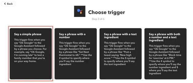
Type the phrase you want to trigger the action. Make sure to specify the trigger command in different ways for example I used
a) turn on the light
b) put on the light
c) put the light on
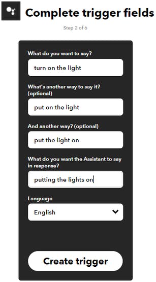
Click on ‘Create Trigger’
Click on ‘+That’

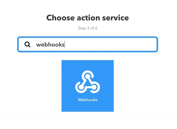
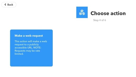
Enter the API URL you got in the previous Step. Make sure that you change the API Key and device name.
Method will be GET
Content type will be Application/json
Here is how your screen will look like
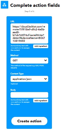
Click on ‘Create Action’ and then Click on ‘Finish’
So whenever we want to turn on the lights, we send a string “f” to the TX line of Bolt.
Now you have to follow same procedure to send strings “d“, “s“, “a” to turn off the lights, turn on the fan and turn off the fan respectively. Use suitable phrases.
The sample code for turning off the light would be:
https://cloud.boltiot.com/remote/f1f918e9-d9c2-4e5b-aed0-b7cb743f74cf/serialWrite?data=d&deviceName=BOLT13819450
That’s it. You are done.
Now wake your Android phone by saying “OK Google” and say the phrase you had set while creating the trigger to use your appliances remotely.
Step 4: Creating an Android application using MIT App Inventor2
Go to MIT App Inventor by clicking here. Create a free account and click on Create Apps! Then click on Start new project.
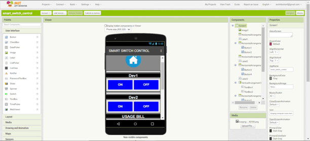
Below is the design of the app I created. You can view the components I added on the right side.
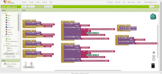
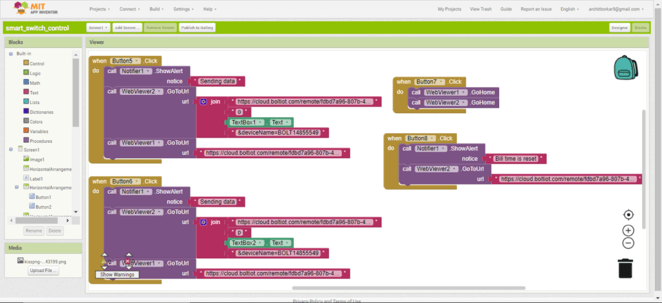
After the design is complete, click on the Blocks tab besides Designer tab. And add the blocks to get the following sketch on Screen1. Note that Webviewer1 sends the Serial data and Webviewer2 receives the incoming data.
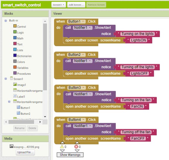
Create four more Screens with names LightsON, LightsOFF, FanON and FanOFF.
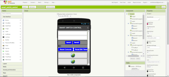
Below is the image of Screen LightsON.
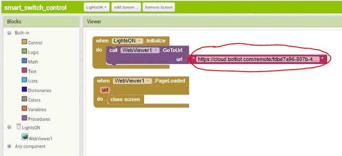
Create similar blocks for rest of the three screens.
Remember to change the URL highlighted in red color with the commands we created before that is:
https://cloud.boltiot.com/remote/API_KEY/serialWrite?data=STRING&deviceName=DEVICE_ID
The parameters that you need to replace are:
API_KEY: You can get it from API tab on cloud dashboard.
STRING: This is the string that we will send to Arduino through Bolt. ( “f”, “d”, “s”, “a”)
DEVICE_ID: The ID of your device. You can get it from cloud dashboard.
Get the .apk file from BUILD tab and your android app is ready!
The link for .apk file is given below:
https://github.com/Archit-09/Smart-Switch-Controller.git
Step 4: Upload code to the Arduino board
Upload the below given code into the Arduino.
NOTE: WHILE UPLOADING THE CODE TO THE ARDUINO BOARD DISCONNECT THE TX AND RX PINS TO THE BOLT MODULE.
https://github.com/Archit-09/Smart-Switch-Controller.git
#include <Servo.h>             //Servo library
#include <stdlib.h>
Servo servo;
//initialize a servo object for the connected servo
int angle;                     //angle of servo
#define motp 3                 //movement motor
#define motn 4
#define eco 11                 //distance sensor
#define trig 12
#define led 7                  //indicator led
long duration;
int pos=1,temp,tempC,distance,tym=0,l=0,f=0,i,j;
 //pos = position of motor; temp, tempC = temperature, in Celsius; l = light, f = fan
float t=0,t1=0,t2=0;
 //t = timer for 30 seconds repositioning, t1 = timer for light, t2 = timer for fan
String fray;
float bill1 = 0,bill2 = 0;
 // bill1 = bill of device 1 (light) , bill2 = bill of device 2 (fan)

void setup()
{
  Serial.begin(9600);
  servo.attach(2);
  //attach the signal pin of servo to pin2 of arduino
  servo.write(28);
  //set the initial angle of servo to 28 degree
  pinMode(3,OUTPUT);
  pinMode(4,OUTPUT);
  pinMode(10,OUTPUT);
  pinMode(trig,OUTPUT);
  pinMode(eco,INPUT);
  pinMode(led,OUTPUT);
}


void loop()
{
  if(tym > 10800)
  //if device on for 3 hours then switched off automatically
  {
    if(pos == 1)
    {
       tog_off();
       fanP();
       tog_off();
       lightP();
       t = 0;
       l=0;
       tym = 0;
      }
    else if(pos == 2)
      {
       tog_off();
       lightP();
       tog_off();
       t = 0;
       l=0;
       tym = 0;
      }
  }
  temp = analogRead(A1);
  //measure the temperature of the room
  temp = (temp*500)/1023;
  tempC = temp;


  if (Serial.available())
  {
    String x = Serial.readString();    //string read from bolt cloud
    //Serial.println(x);
    if(x == "a")
    {              // case 1 fan off
      digitalWrite(led,HIGH);
      delay(100);
      digitalWrite(led,LOW);
      if(pos == 2)
      {
       tog_off();
       t = 0;
       f=0;
       tym = 0;
      }
      else if(pos == 1)
      {
       fanP();
       tog_off();
       t = 0;
       f=0;
       tym = 0;
      }
    }
    else if(x == "s")                 //case 2 fan on
    {
      digitalWrite(led,HIGH);
      delay(100);
      digitalWrite(led,LOW);
      if(pos == 2)
      {
       tog_on();
       t = 0;
       f++;
       tym = 0;
      }
      else if(pos == 1)
      {
       fanP();
       tog_on();
       t = 0;
       f++;
       tym = 0;
      }
    }
    else if(x == "d")                  //case 3 light off
    {
      digitalWrite(led,HIGH);
      delay(100);
      digitalWrite(led,LOW);
      if(pos == 1){
       tog_off();
       t = 0;
       l=0;
       tym = 0;
      }
      else if(pos == 2)
      {
       lightP();
       tog_off();
       t = 0;
       l=0;
       tym = 0;
      }
    }
    else if(x == "f")                  //case 4 light on
    {
      digitalWrite(led,HIGH);
      delay(100);
      digitalWrite(led,LOW);
      if(pos == 1)
      {
       tog_on();
       t = 0;
       l++;
       tym = 0;
      }
      else if(pos == 2)
      {
       lightP();
       tog_on();
       t = 0;
       l++;
       tym = 0;
      }
    }
    else if(x.startsWith("o"))
    {
      digitalWrite(led,HIGH);
      delay(100);
      digitalWrite(led,LOW);
      j = x.length();
      fray = x.substring(1);
      float z = fray.toInt();
      z = z/1000;
      bill1 = ((z*t1*2.5)/(60*60));
    // calculation to find electricity bill in INR
      Serial.println("Bill = " + String(bill1,6) + " INR" + " ");
      j = 0;
    }
    else if(x.startsWith("p"))
    {
      digitalWrite(led,HIGH);
      delay(100);
      digitalWrite(led,LOW);
      j = x.length();
      fray = x.substring(1);
      float z = fray.toInt();
      z = z/1000;
      bill2 = (z*t2*2.5/(60*60));
     // calculation to find electricity bill in INR
      Serial.print("Bill = " + String(bill2,6) + " INR" + " ");
      j = 0;
    }
    else if(x == "l")
    {
      digitalWrite(led,HIGH);
      delay(100);
      digitalWrite(led,LOW);
      t1 = 0.0;
      t2 = 0.0;
      bill1 = 0.0;
      bill2 = 0.0;
    }
  }

  if(tempC >= 35)
  //temperature gone above 35 deg C turn on the fan
    {
      if(pos == 2)
      {
       tog_on();
       t = 0;
       f++;
       tym = 0;
      }
      else if(pos == 1)
      {
       fanP();
       tog_on();
       t = 0;
       f++;
       tym = 0;
      }
    }

  if(l>0 || f>0)
  {
    tym = tym + 0.307;
    t1 = t1 + 0.307;
    t2 = t2 + 0.307;
  }

  manual();                   // check gesture controls

  delay(100);
  t = t + 0.307;
// for repositioning the servo after 30 sec of use
  if(t >= 60 && pos == 2){
    lightP();
  }
}

void lightP()                 // function- light position
{
  digitalWrite(motp,HIGH);
  digitalWrite(motn,LOW);
  delay(13000);
  digitalWrite(motp,LOW);
  digitalWrite(motn,LOW);
  pos = 1;
}

void fanP()                   // function- fan position
{
  digitalWrite(motp,LOW);
  digitalWrite(motn,HIGH);
  delay(13000);
  digitalWrite(motp,LOW);
  digitalWrite(motn,LOW);
  pos = 2;
}

void tog_off()                //toggle off
{
  servo.write(0); //off
  delay(1000);
  servo.write(28);
}

void tog_on()                 //toggle on
{
  servo.write(50); //on
  delay(1000);
  servo.write(28);
}

void manual()                            //gesture control
{
  digitalWrite(trig,LOW);
  delayMicroseconds(2);
  digitalWrite(trig,HIGH);
  delay(200);
  digitalWrite(trig,LOW);
  duration=pulseIn(eco,HIGH);
  distance=duration*0.034/2;
  if(distance<=20)
  //if distance less than 20cm turn off light and fan
  {
    digitalWrite(led,HIGH);
    delay(100);
    digitalWrite(led,LOW);
    if(pos == 2)
    {
       tog_off();
       lightP();
       tog_off();
       t = 0;
       l=0;
       tym = 0;
    }
    else if(pos == 1 && f>0 && l>0)
    {
       fanP();
       tog_off();
       t = 0;
       l=0;
       f=0;
       tym = 0;
       lightP();
       tog_off();
    }
    else if(pos == 1 && l>0)
    {
        tog_off();
        t = 0;
        l = 0;
        tym = 0;
    }
    else if(pos == 1 && f>0)
    {
       fanP();
       tog_off();
       t = 0;
       f=0;
       tym = 0;
       lightP();
    }
  }
  else if(distance>=20 && distance<=40)
  //if distance is 20cm to 40cm turn on the light
  {
      digitalWrite(led,HIGH);
      delay(100);
      digitalWrite(led,LOW);
      if(pos == 1 )
      {
        tog_on();
        t = 0;
        l++;
        tym = 0;
      }
      else if(pos == 2)
      {
        lightP();
        tog_on();
        t = 0;
        l++;
        tym = 0;
      }
  }
}
The code takes care of some advance functions:
- The LM35 temperature sensor collects the temperature data of the room and when the temperature of the room crosses 35 degree Celsius the fan is put on automatically.
- When any appliance is left working for more than 3 Hours it automatically switches off all the appliances.
- If the hand gesture distance from the Ultrasonic sensor is less than 20cm the appliances are turned off whereas if the distance of gesture is 20cm to 40cm it turns on the appliance.
- The basic structure of the code is – Whenever we use Ok Google or the Android App, the strings ( “f”, “d”, “s”, “a”) are sent to Arduino by Bolt Wi-fi module using the Bolt IoT cloud UART communication. And when these strings are received by Arduino the particular functions occur.
- Code also carries the calculation for electricity bill of appliances it controls using the time for which the appliance has been working. All that the user have to do is, send the power consumption of the appliance in Watts.
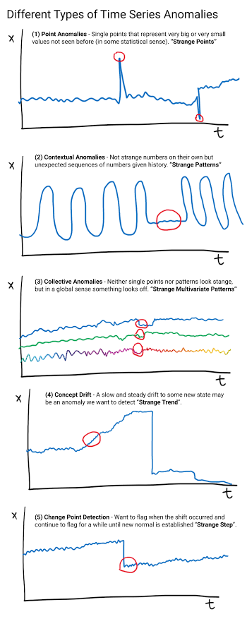
Step 4: Contextual anomaly detection code
Below image shows some types of anomalies. Since this project involves finding anomaly in everyday pattern of light, we have to use contextual anomaly.
Below are the steps to achieve contextual anomaly detection and alert using Bolt WiFi module. I have used Linux Mint operating system.
Create a .py file with name conf.py and add the below code to it.
SSID = 'You can find SSID in your Twilio Dashboard'
AUTH_TOKEN = 'You can find  on your Twilio Dashboard'
FROM_NUMBER = 'This is the no. generated by Twilio. You can find this on your Twilio Dashboard'
TO_NUMBER = 'This is your number. Make sure you are adding +91 in beginning'
API_KEY = 'This is your Bolt Cloud account API key'
DEVICE_ID = 'This is the ID of your Bolt device'
FRAME_SIZE = 1440
Create a new file in same directory in which conf.py is placed and name it Contextual_anomaly.py and add the below given code to it.
import conf, json, time, math, statistics
from boltiot import Sms, Bolt
mybolt = Bolt(conf.API_KEY, conf.DEVICE_ID)
sms = Sms(conf.SSID, conf.AUTH_TOKEN, conf.TO_NUMBER, conf.FROM_NUMBER)
history_data = []
i = 0
while True:
response = mybolt.analogRead('A0')
data = json.loads(response)
if data['success'] != 1:
print("There was an error while retriving the data.")
print("This is the error:"+data['value'])
time.sleep(10)
continue
print ("This is the value "+data['value'])
sensor_value=0
try:
sensor_value = int(data['value'])
except e:
print("There was an error while parsing the response: ",e)
continue
if i<=1440:
print("Not enough data to detect anomaly. Need ",conf.FRAME_SIZE-i," more data points")
elif i>1440:
if sensor_value > history_data[i-conf.FRAME_SIZE] + 20 :
print ("The light level increased at uncertain time. Sending an SMS")
response = sms.send_sms("Someone turned on the lights")
print("This is the response ",response)
elif sensor_value < history_data[i-conf.FRAME_SIZE] - 20 :
print ("The light level decreased at uncertain time. Sending an SMS")
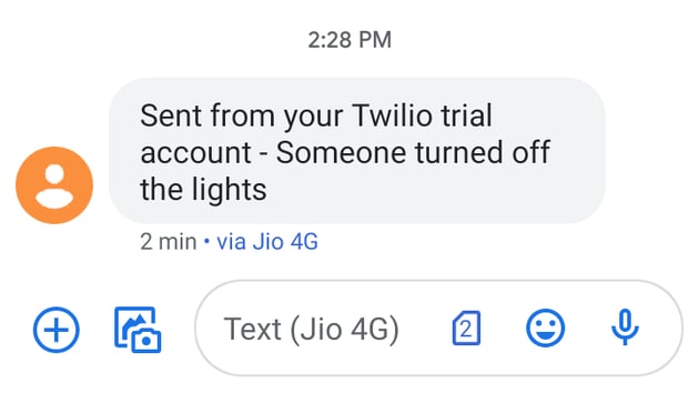
response = sms.send_sms("Someone turned off the lights")
print("This is the response ",response)
history_data.append(sensor_value);
history_data.append(int(data['value']))
time.sleep(60)
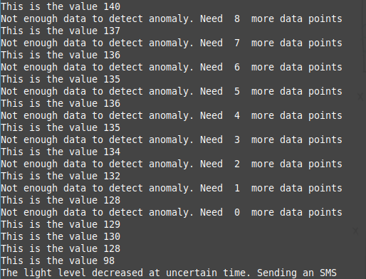
i += 1To run the code use the below command in terminal.
sudo python3 Contextual_anomaly.pyBelow is an image of the terminal after executing the code successfully.
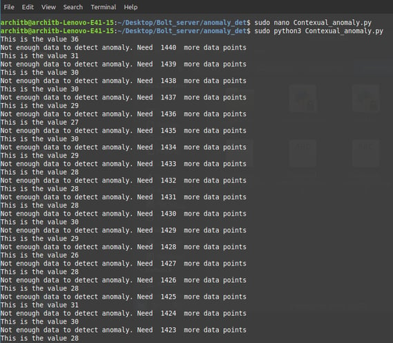
LDR sensor value is collected every minute for one day to understand the lighting pattern. Thus total 60*24 = 1440 values are collected. This data is compared with the data at same time on next day and consecutive days and if the difference is more than 20 value or less than -20 value then the anomaly in light pattern is detected and SMS through Twilio account is sent on phone.
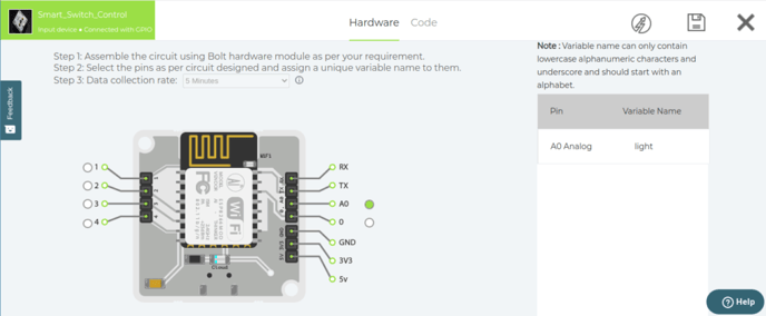
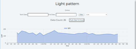
The light pattern can be observed visually by using Bolt cloud .js code editor. To view this graphically log in to the Bolt cloud.
Create a new product, give an appropriate name and select INPUT and GPIO options in the product setup.
In hardware configuration choose A0 pin of bolt and give name to the input pin which has LDR.
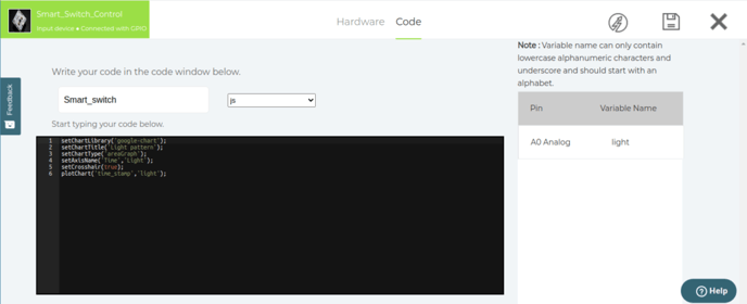
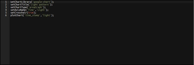
In code configuration choose .js file extension and give it an appropriate name. The code to view an area graph is as given below :
Demonstration
1. The video demonstration below shows the remote controlling of the switches using three methods- OK google, Android App and hand gesture.
2. User can use the android app to provide the power consumption of an appliance and get the electricity bill.
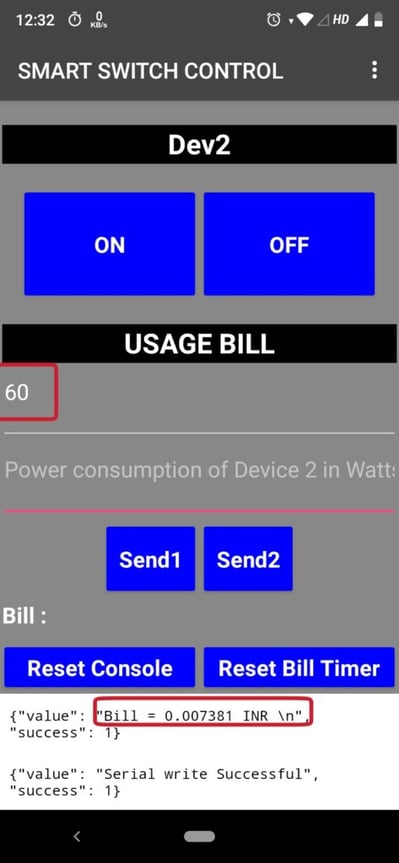
In calculation above the power consumption for light is given as 60 Watts and the time for which the light was left On is approximately 3 minutes which is 180 seconds. Thus the calculation proceeds as :
Bill = ((P (Watts)*time (sec))/(1000*60*60)) KWh * Cost per unit (INR)
Bill = ((60*180)/(1000*60*60))*2.5 (assuming cost per unit is 2.5 INR)
Bill = 0.0075 INR (As can be observed in the console of app)
3. Below demonstration shows the alert as a message after detecting an anomaly in the regular everyday pattern in light schedule
The graphical view of light can be seen by choosing the “view this device” option on Bolt cloud product. The graph obtained is as shown below:
SCOPE FOR APPLICATIONS
- Consider you are very tired and you are driving back home. After reaching home you have to switch on the geyser and wait for 15 to 20 minutes for the water to get hot. But if this switch controller is placed onto the switchboard having the geyser switch then you can turn it ON remotely and after reaching home you can save your time.
- To turn ON the air cooler in your room you no longer have to get up and turn it ON, just use the phone as remote or voice command and work is done. You can also easily use this device for the fan in the season when Cooler won’t be required.
- The portability of device allows the user to take it anywhere and convert any room into a smart room.
- Anomaly prediction protects from theft and robbery by keeping track on everyday light pattern.
- Electricity bill can be tracked and saved by understanding the increase in bill as per the appliance usage.
Conclusion
That’s it! A similar hardware arrangement as seen in the image or video can be made as per the requirement of the switchboard and you can convert any room into a smart room.
Use the Google Assistant or Android App or even Hand Gesture to control any appliances in your house, in any room of your house or even in any other building and house as it is a portable device.
Want to build more such IoT and ML projects? Want to learn IoT and ML from basics?
Check out the Bolt IoT and ML training. This online video training is excellent for those who want to start with IoT and ML because it teaches you to build projects from the basics. Click on the button below to know more about the training.