I hope you got the "green light" signal from your brain, to start building this project. This Project was done based on my observations of the Traffic Management Systems in Roadways and Railways. I thought I would make a miniature replica of the same using the Bolt WiFi module.


Using the Components mentioned above in the list, we can create a Traffic Light Control Circuit. But what are the steps to be done in order to perform it?
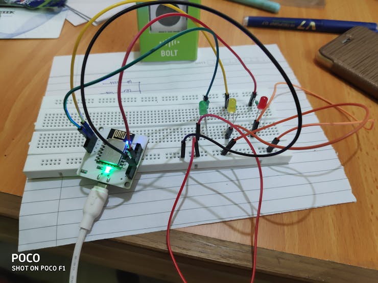
First Connect your Bolt IOT Module to your PC/Laptop using the Micro USB - USB Cable
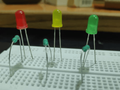
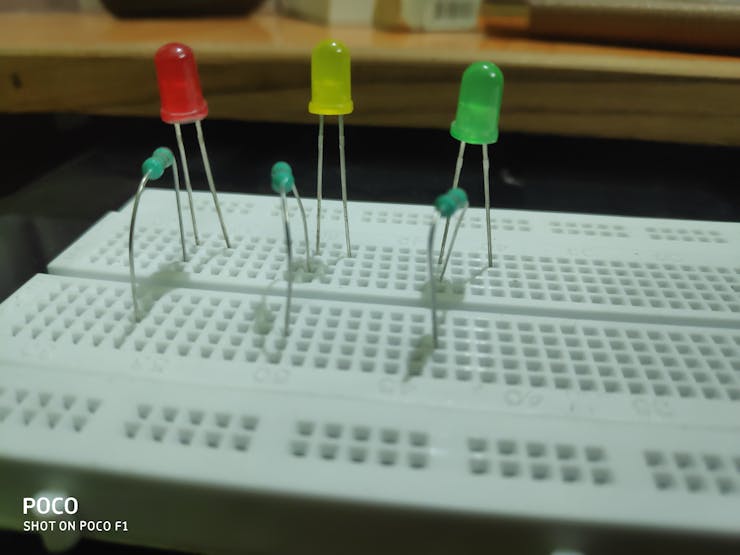
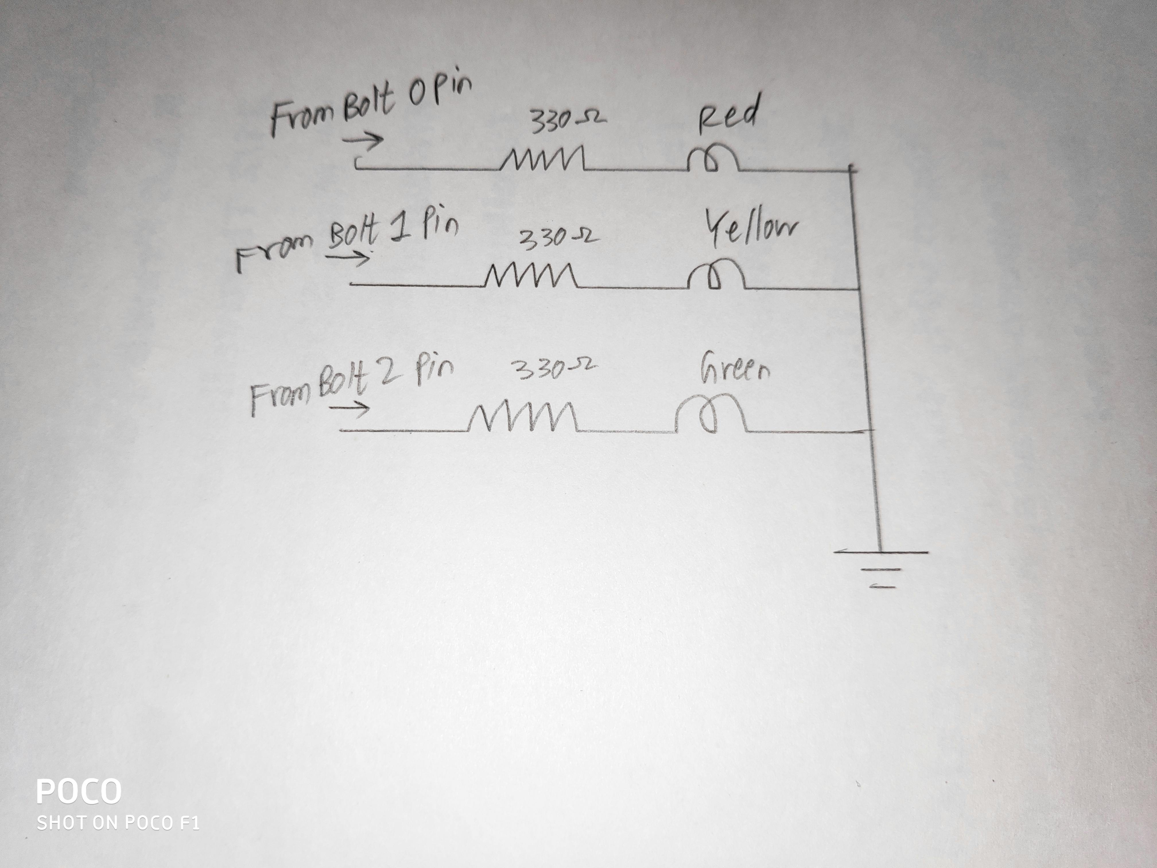
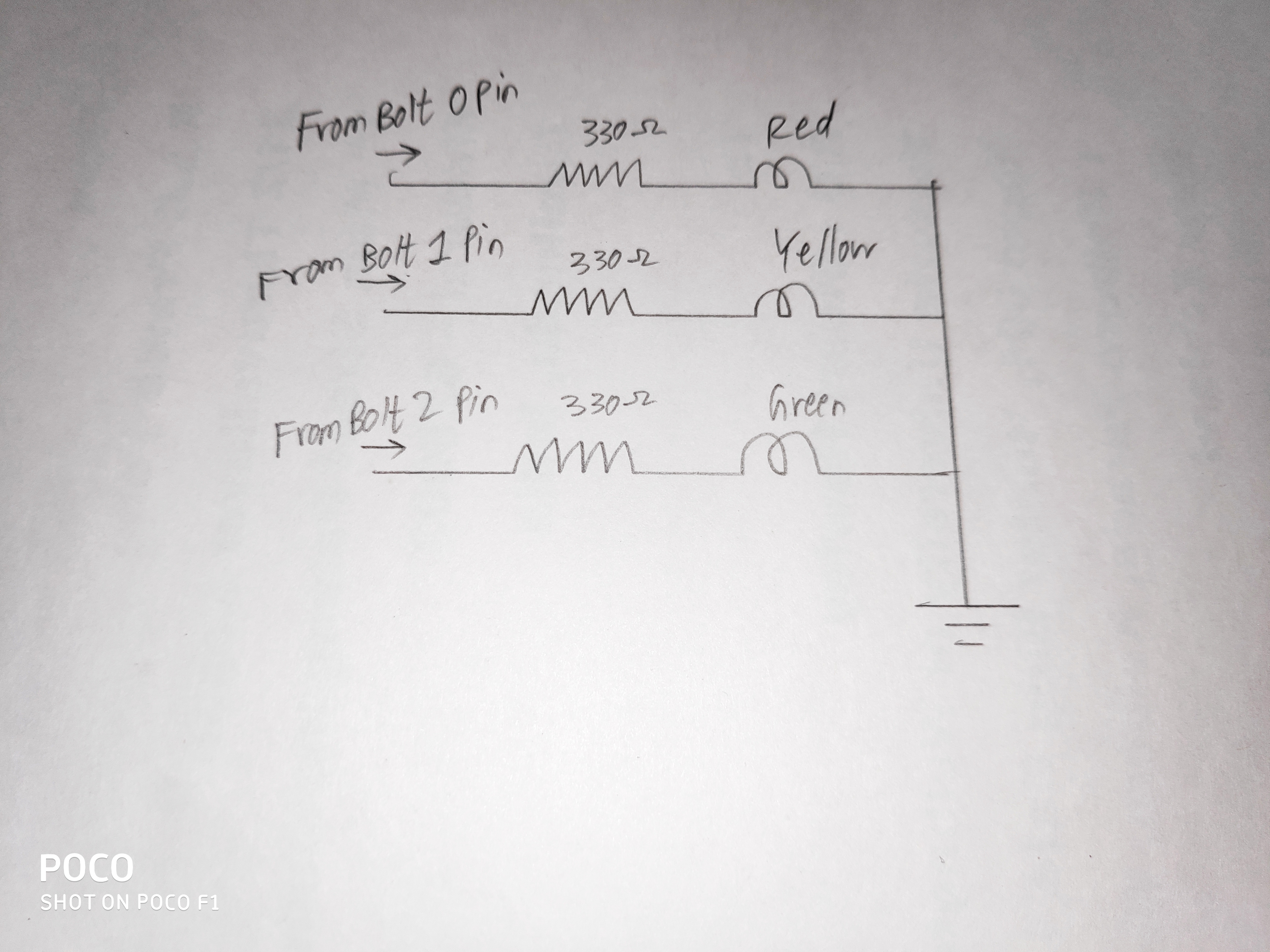
Note: The Steps given below are done on the Breadboard
Step 3] The Other end of the Resistor from RED/YELLOW/GREEN LED is connected to the Digital Pins 0, 1 and 2 of the Bolt IOT Module through Male-Male Jumper Wires.
Step 4] The Ground pin from the BOLT IOT Module is made Accessible on the One End of the Breadboard.
Step 5] The Negative End ( Shorter Leg ) of Each LED is Connected is connected to the Ground of the Bolt IOT Module.
The Complete Connection is Given Below.
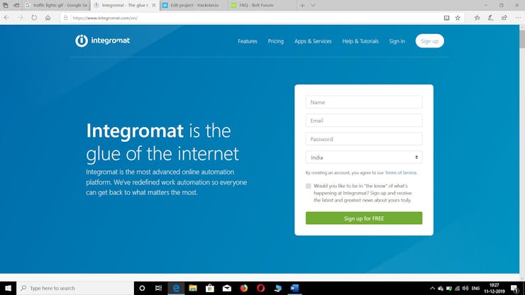
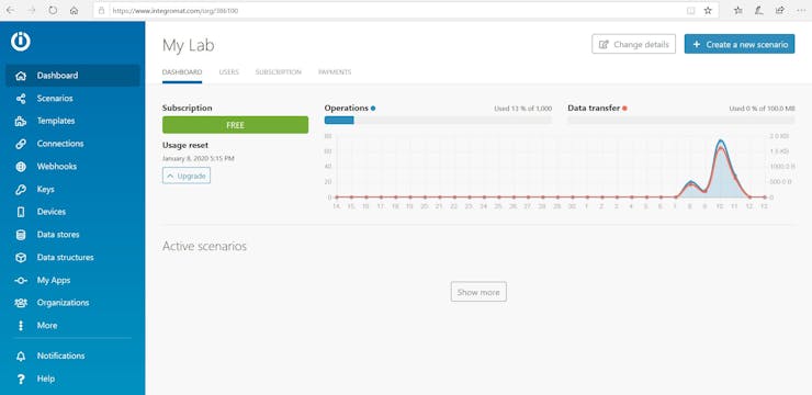
Step 1] Setup an Account on Integromat Software.
Step2] After creating an account in Integromat, You will be in the Page called My Lab. Select "Create New Scenario" Button which is located on the Top Right Corner of your page.

The create scenario page will be Like this.
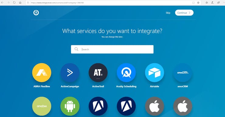
Step 3]Type Bolt IOT in the Search Box or You can Scroll Down and find the Bolt IOT Icon.
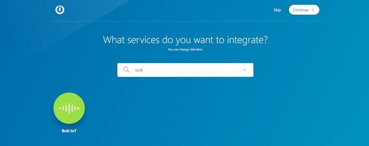
Step 4] Select the Bolt IOT Icon and Click Continue. Your Window Will be Displayed Like This.
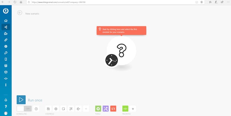
Step 5] Select the ? Icon and Click on Bolt IOT. The Module will ask for Connection and Command. Click on Add Connection, it will ask for API key and Connection Name. Give a Suitable Connection Name and Simultaneously Open Bolt Cloud in your Browser. Select the API Keys Tab.
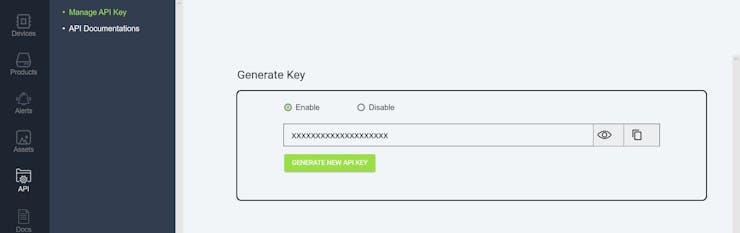
Step 6] The API Key will be Displayed. Copy the API Key and Paste it in the API Key Box. Now the Bolt Cloud is Interlinked with Integromat.
Step 7] Now Select the Command Box. It Drops down into a List. In the GPIO List, Select Write Digital Output.
The Box would be something like this
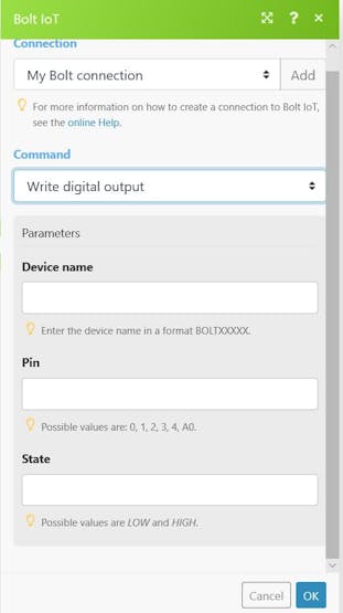
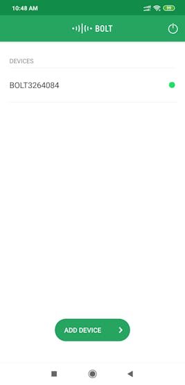
Step 8]To Find Your Device Name, Make sure that you have Downloaded the Bolt IOT App from PlayStore or App Store and Linked the Bolt Cloud with Bolt App.The Device Name will be Displayed in the App. Note Down the Device Name
The Name of the Device must ne Entered in the Device name Box. In the Pin Box Type 0 and in the State Box Type "High". Then Select Continue.
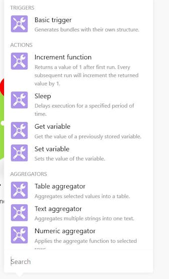
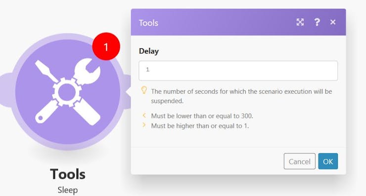
Step 9] Then Select Tools Icon ( The Purple Icon which is given in the Bottom ).
Select Sleep Option and Link it with the Bolt Module. Set Delay as per your requirement for Red Signal.
Then Add Another Bolt Module next to the Tools Icon, Select the Same Connection and Same Command as mentioned above.

Once Again type the Device Name, Pin No. (0) and in the state Box, Type Low.
Repeat the Steps 4, 5 and 6 for Yellow Signal (Digital Pin 1) and Green Signal (Digital Pin 2).
Step 10] The Overall Connection in the Integromat Software will look like this.
The Above method switches on each Colour Signal only one Time. If we need to make the Traffic Signal Switch On for a Certain Number of Times, we need to use a New Function in the Flow Control Box.
.
Flow Control Box can be opened at the Bottom Toolbar. It is Close to the Tools Icon which we used earlier.
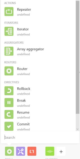
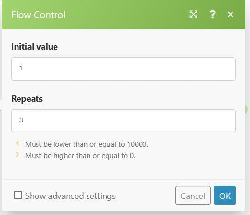
Step 11] Select Repeater from the Flow Control Tool and Link the Repeater to the Starting Bolt Icon. Set the Initial Value as 1 and in the Repeats Box, select any value between 0-10000. For my use and ease, I choose 3.
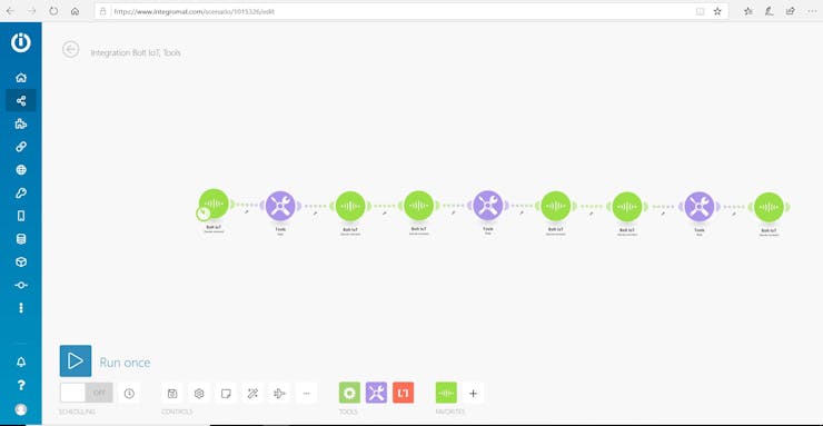
Step 12] The Total Circuit would look like this.
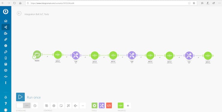
Step 13] Click Run Once and you will find your Traffic Light Working.
This is just an Reference Diagram
This Project provides the reader/user the beneficial things IoT can do to the Traffic Management System. This Project also covers the usage of Integromat Software which has various uses in the field of IoT and AI.
Check out the Bolt IoT and ML training. This online video training is excellent for those who want to start with IoT and ML because it teaches you to build projects from the basics. Click on the button below to know more about the training.
Get the latest IoT tutorials, projects, and updates delivered to your inbox.