Control Any Elevator Using Your Smartphone
The coronavirus pandemic has changed our daily lifestyle, as protection of oneself from this virus include wearing of masks, regular cleaning of hands, etc. The virus is notable for spreading easily through cough drops in the air, touching of common surfaces including currency, elevator buttons, doorbells, etc.
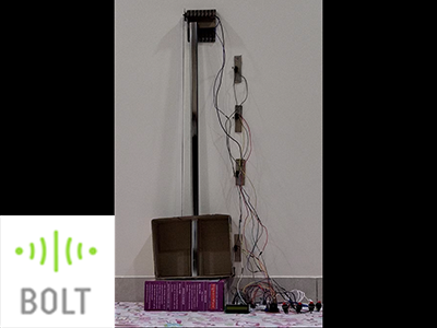
This project demonstrates the implementation of Bolt IoT in any commercial elevator, enabling users to control it using their smartphone, in an attempt to reduce the touching of the elevator buttons.
Things used in this project
Hardware components -
- Bolt IoT Wi-Fi Module: Used to pass commands to the Arduino via UART (Universal Asynchronous Receiver-Transmitter) communication.
- Arduino Mega 2560: To operate the elevator i.e. the motor, buttons, limit switches and the LCD, the Arduino module is used.
- Limit Switch: The limit switch is a type of switch which is actuated by a lever. It has 3 terminals, the common terminal is used as the voltage supply. On pressing the lever, the current is redirected from the NC (Normally Closed) terminal to the NO (Normally Open) terminal. * 4 switches
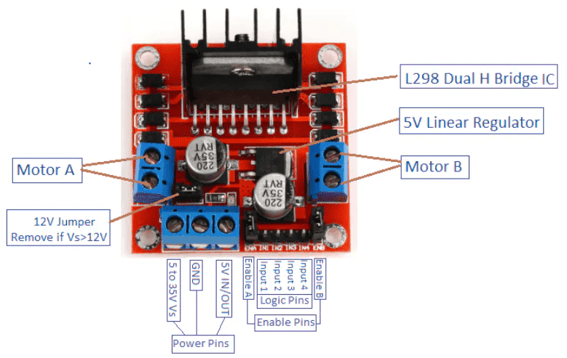
- Motor driver: To ensure that the DC motor runs using Arduino, an interface is required. This is the motor driver, which is an H-bridge transistor. In the project, the L298 motor driver is used, which a generic component.
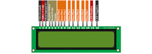
- LCD Display: An LCD with Hitachi HD44780 driver is a generic component used in many applications. A 16×2 LCD is sufficient to display all the parameters of the elevator. An LCD Display with female header pins will prove easier to make the connections. The connections and code given here are for just using the LCD with Arduino. If you want to reduce the number of connections, then you can integrate an I2C adapter with the LCD, for which the connections or code are not mentioned in the project.
- DC Motor: It is recommended to use a high torque stepper motor to adapt to the loads.
- Pushbutton Switch: This is an optional component as I used it to operate my elevator the conventional way. * 4 buttons.
- Solderless Breadboard Full Size: It is recommended to use a full-size breadboard, although the one in the Bolt IoT starter kit can be used but will
- Male/Male Jumper Wires * 30 (approx.)
- Male/Female Jumper Wires * 4 (approx.)
- Breadboard wire: These will be used to connect the components without header pins to the breadboard. I used about 10 metres of the wire for my project.
- Resistor 1k Ohm: * 11
Software components -
- Sublime text 3: Used for coding in HTML, PHP and javascript
- Arduino IDE: For programming the Arduino Mega 2560
- Android Studio: For integrating the webpage with Android WebView.
Alternatively, the complete mobile application can be made using Android Studio itself, the procedure or code for which is not given in the project. - XAMPP: Used for making the databases to be accessed via the mobile app on the local internet.
Hardware Setup
To start, the connections to the Arduino are:
Step 1:Connection to Bolt IoT
Step 1.1: Connect the RX0 pin (pin 0) of Arduino to TX pin of the Bolt
Step 1.2: Connect the TX0 pin (pin 1) or Arduino to RX pin of the Bolt
Step 2: Connection to push buttons:
Step 2.1: Connect pin 24 of Arduino to one end of Ground floor button, the same end of the button will be connected to ground via a 1k Ohm resistor. Connect the other end of the button to 5V supply.
Step 2.2: Connect pin 25 of Arduino to one end of floor 1 button, the same end of the button will be connected to ground via a 1k Ohm resistor. Connect the other end of the button to 5V supply
Step 2.3: Connect pin 26 of Arduino to one end of floor 2 button, the same end of the button will be connected to ground via a 1k Ohm resistor. Connect the other end of the button to 5V supply
Step 2.4: Connect pin 27 of Arduino to one end of floor 3 button, the same end of the button will be connected to ground via a 1k Ohm resistor. Connect the other end of the button to 5V supply
Step 3 :Connection to limit switches (floor sensor)
Step 3.1: Connect pin 21 of Arduino to the NO (Normally Open) end of Ground floor limit switch, the NO end is also connected to ground via a 1k Ohm resistor. Common end of the limit switch is connected to 5V supply.
Step 3.2: Connect pin 20 of Arduino to the NO end of floor 1 limit switch, the NO end is also connected to ground via a 1k Ohm resistor. Common end of the limit switch is connected to 5V supply.
Step 3.3: Connect pin 19 of Arduino to the NO end of floor 2 limit switch, the NO end is also connected to ground via a 1k Ohm resistor. Common end of the limit switch is connected to 5V supply.
Step 3.4: Connect pin 18 of Arduino to the NO end of floor 3 limit switch, the NO end is also connected to ground via a 1k Ohm resistor. Common end of the limit switch is connected to 5V supply.
Step 4 : Connection to the motor driver
Step 4.1: Connect pin 22 of Arduino to input pin 1 of the motor driver
Step 4.2: Connect pin 23 of Arduino to input pin 2 of the motor driver
Step 4.3: Connect pin 8 of Arduino to bottom pin of enable A block of the motor driver (for controlling the speed of the motor, if not required then put a female-to-female jumper on both enable pin A terminals)
Step 4.4: Connect pin 9 of Arduino to top pin of enable A block of the motor driver (for controlling the speed of the motor, if not required then put the jumper on both enable pin A terminals)
Step 4.5: Connect 5V pin of Arduino to VCC and 5V power pins of the motor driver. Make sure to remove the 12V jumper from the motor driver, and connect the GND pin of the motor driver to GND of Arduino
Step 4.6: Connect each terminal of the motor A block to each end of the motor
This is to be done if you’re using your Arduino to power the motor controller (although this will consume more power from the Arduino and the LCD may go dim). There are other ways to do it too. You can check out this link for using other methods to power up the motor controller.
For an idea of the schematic of the motor controller, check out the diagram below
Step 5 : Connection to the LCD Display
Step 5.1: Connect the VSS pin (pin 1) of the LCD to ground
Step 5.2: Connect the VCC pin (pin 2) of the LCD to 5V
Step 5.3: Connect the V0 pin (pin 3) of the LCD to ground via a 3.3k Ohm resistor (or three 1k Ohm resistors in series)
Step 5.4: Connect the RS pin (pin 4) of the LCD to pin 12 of Arduino
Step 5.5: Connect the R/W pin (pin 5) of the LCD to ground
Step 5.6: Connect the EN pin (pin 6) of the LCD to pin 11 of Arduino
Step 5.7: Connect the D4 pin (pin 11) of the LCD to pin 5 of Arduino
Step 5.8: Connect the D5 pin (pin 12) of the LCD to pin 4 of Arduino
Step 5.9: Connect the D6 pin (pin 13) of the LCD to pin 3 of Arduino
Step 5.10: Connect the D7 pin (pin 14) of the LCD to pin 2 of Arduino
Step 5.11: Connect the A pin (pin 15) of the LCD to 5V
Step 5.12: Connect the C pin (pin 16) of the LCD to ground
For an idea of the pins on the LCD, refer the diagram below:
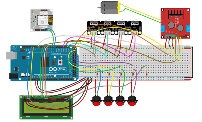
The Schematic for the connections is given below
Software Programming
Step 1:
XAMPP is used to make MySQL databases which store the elevator details (the building the elevator’s located in, number of floors above, on and below the ground) and the corresponding credentials to access the elevator (device name and API key of the bolt module). The bolt’s credentials, though stored in the database, are not directly accessible by the user.
Let’s look at the databases made using xampp:
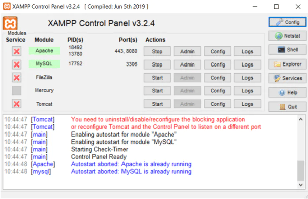
To begin with, open xampp by going to start, then searching for “xampp” and clicking on XAMPP Control Panel. In the application window, click the Start button under Actions for Apache and MySQL rows.
The XAMPP window should look like this:
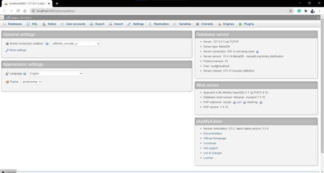
Step 2:
Now, click on the Admin button under the MySQL row. You will see the MySQL admin loaded in your browser. It will look like this:
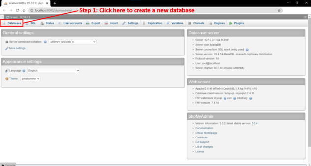
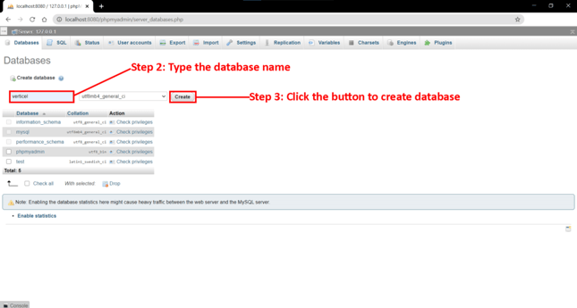
Step 3:
Click on the Databases button, then under Create database, type the database name you want to create in the text field (I used the name verticel) and click create. This will the database name to be used in all PHP codes in the project. Then click on the database name (verticel) in the list of databases, and then a new page will appear. The tables can be made here as given below:
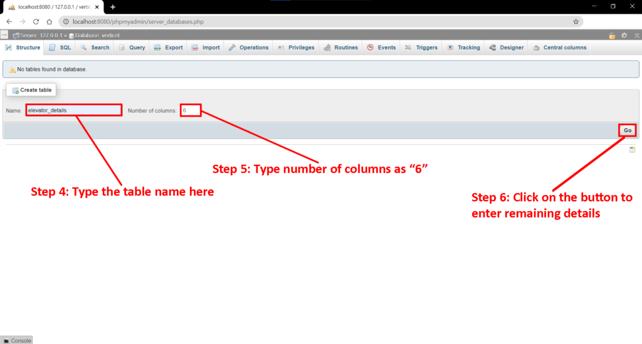
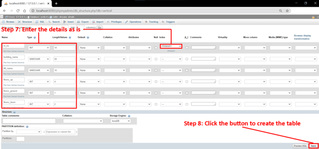
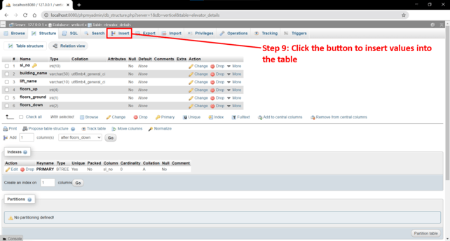
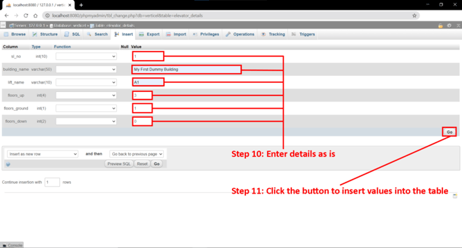
Step 4:
The following pictures will guide you to create the table elevator_details which will be storing the details of the elevator to be displayed in the front end of the application
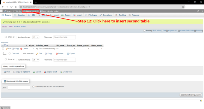
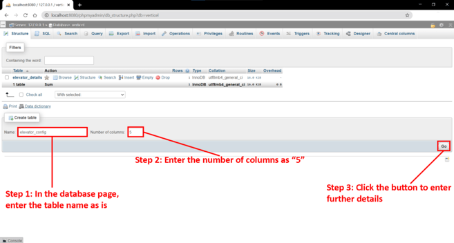
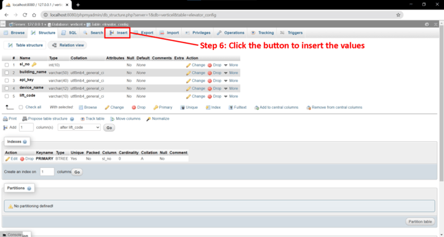
Step 5:
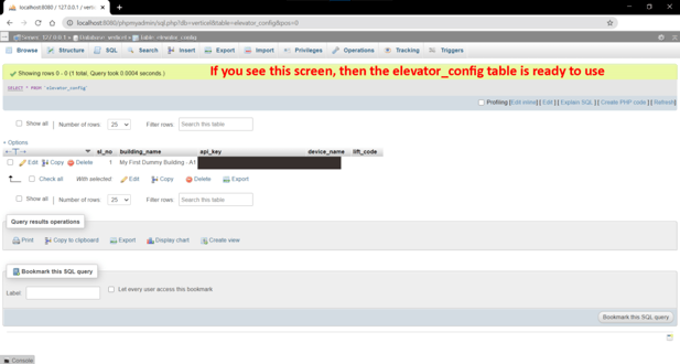
The following pictures will guide you to create the table elevator_config which will be storing the details of the bolt module used in the elevator and the random code used to access it. This random code will prevent any misusage of the elevator.
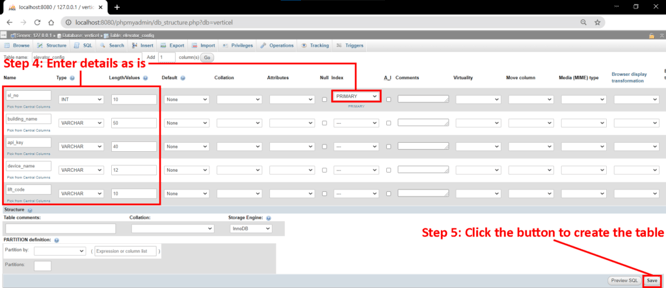
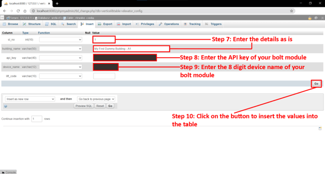
You can get your API Key and Device ID/Device Name from your Bolt Cloud Dashboard. The Device Name should be entered in the database omitting the word BOLT i.e. only the numbers need to be entered in the database.
Never share the device name and API key with others as it may lead to unauthorized and unwanted access to the device. In case you feel that the bolt device is hacked by someone, simply generate a new API key.
Step 6: Resolving Errors
On clicking Start in XAMPP, in case a message appears which looks like this, then try changing the ports for the servers. Below the picture is the information for changing the ports in XAMPP.
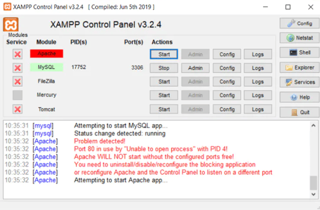 Error in XAMPP due to the serverport 80 being used by another application
- Changing the main port: Click on the Config button in the Apache row, then click on Apache (httpd.conf) in the dropdown list. In the notepad window, change the number 80 to something else (in my case, I used 8080) at the two places, then close the notepad window after saving:
Listen 80 to Listen 8080 at line 60
ServerName localhost:80 to ServerName localhost:8080 at line 228
- Then click on the Config button (the one with a wrench on its left), then click on the Service and Port Settings button in the pop-up window, in the second pop-up window, change the Main Port to the number you set in the first step (in my case, 8080).
- Changing the SSL port: If the error message still appears, then try changing the port from 443 to something else (I chose 4433) in Config -> Apache (httpd-ssl.conf):
Listen 443 to Listen 4433 at line 36
<VirtualHost _default_:443> to <VirtualHost _default_:4433> at line 121
ServerName www.example.com:443 -> ServerName www.example.com:4433 at line 125
- Then again click on the Config button (the one with a wrench on its left), then click on the Service and Port Settings button in the pop-up window, in the second pop-up window, change the SSL Port to the number you set in the first step (in my case, 4433).
- Now, whenever you’re opening any HTML or PHP page through the XAMPP server, make sure you type localhost:8080 (or localhost:port_name) if you’ve changed the main port.
Step 7:
To design the webpages for the project, I used Sublime Text 3, which is free to use. To make sure the code works over the local network, all the files and folders must be stored in the location in the computer pointed out below:
- A folder named verticel inside the directory C:\xampp\htdocs (given that XAMPP is installed in the default installation location. In case XAMPP is installed somewhere else, then go to xampp, then htdocs and then create the folder verticel)
The codes to be saved in the folder are given in this link.
- A folder named Admin inside the directory C:\xampp\htdocs (same goes for this as well if XAMPP was installed in another location).
The codes to be saved in the folder are given in this link.
Step 8:
After saving the codes, open your browser and open the webpage localhost/Admin/auto_update_lift_code.php and leave it open until the end of the project
The webpage address will change if the Main Port is changed in XAMPP. In that case, open the webpage by including a :PortNumber after localhost. For eg., if the Main Port is 8080, then the address will be localhost:8080/Admin/auto_update_lift_code.php
Step 9: Upload the firmware present in the code given in this link to the Arduino. In this code, only the pre-installed libraries were utilized and no additional libraries were installed.
Before transferring the code, ensure that the device selected for debugging/running the code is changed to Arduino Mega 2560 by going to Tools->Board->Arduino Mega or Mega 2560.
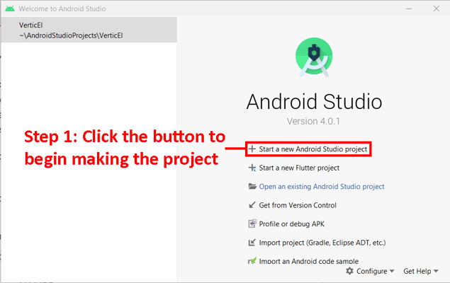
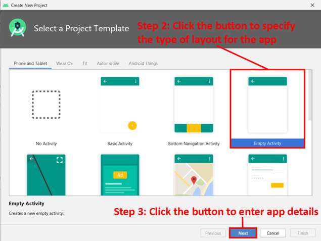
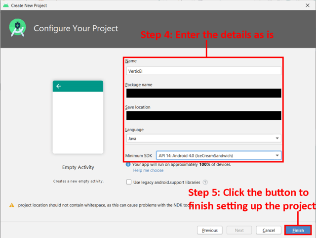
Step 10: Android Studio was used to create the app which runs the webpage verticel.php using the WebView feature.
To create the mobile app, open Android Studio, and follow the steps in the following set of pictures:
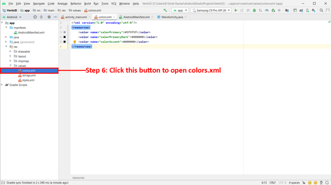
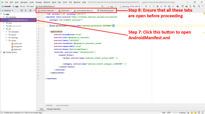
Step 11:
After making sure that the 4 tabs specified in the picture above are open, paste the code which is provided in the project’s resources.
After all the codes are done, connect your phone to the computer via USB cable and switch on the developer mode and ensure that USB debugging is enabled.
To turn on the developer mode in your phone, go to your phone’s settings, then tap on About phone, then tap on Software information, and finally tap on Build number 7 times. This will enable the developer mode. Next, go to the settings main menu and click on Developer options. Search for USB debugging and turn it on while ensuring that the phone is connected to the computer.
After turning on USB debugging, follow the procedure shown in the following picture:
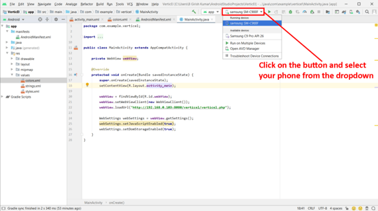
On clicking the button showing your phone in the dropdown list, the application will be installed on the phone and will open. Simply enter the required details in the app to call the elevator.
The codes for inserting in Android Studio are given in this link.
The Video Demonstration
Watch our project in action:
Conclusion
The project successfully demonstrates the implementation of the Bolt IoT in controlling an elevator by using the mobile application VerticEl.
The application is used to search for the building, entering the floor details after selecting the building and entering the code displayed in the LCD panel, which will call the elevator to the source floor, and after getting inside the elevator, it will go to the destination floor, just like how it would happen using normal buttons.
You can see the working of the project in the video in this link.
This concept can be implemented in any commercial elevator with automatic doors and any control module to allow the touch-free movement of people.
Want to build more such IoT and ML projects? Want to learn IoT and ML from basics?
Check out the Bolt IoT and ML training. This online video training is excellent for those who want to start with IoT and ML because it teaches you to build projects from the basics. Click on the button below to know more about the training.