IoT Based Flood Monitoring And Alerting System
As we all know that Flood is one of the major well known Natural Disasters. When water level suddenly rises in dams, river beds etc. Alot of Destruction happens at surrounding places. It causes a huge amount of loss to our environment and living beings as well. So in these case, it is very important to get emergency alerts of the water level situation in different conditions in the river bed.
The purpose of this project is to sense the water level in river beds and check if they are in normal condition. If they reach beyond the limit, then it alerts people through LED signals and buzzer sound. Also it alerts people through Sms and Emails alerts when the water level reaches beyond the limit.
Excited? Let's get started.
Things used in this project
Hardware components -
- Bolt-IoT wifi module
- Arduino uno
- Breadboard- 400 tie points
- 5mm LED:(Green, Red, Orange) and Buzzer
- 16×2 LCD Display
- LM35 Temperature Sensor
- HC-SR04 Ultrasonic Sensor
- Some Jumper Wires
- Male to Female Jumper Wires- 15 pcs
- Male to Male Jumper Wires- 10 pcs
- Female to Female Jumper Wires- 5 pcs
- 9v Battery and Snap Connector
- USB Cable Type B
Software components -
- Arduino IDE
- Python 3.7 IDLE
- Bolt IoT Cloud
- Bolt IoT Android App
- Twillo SMS Messaging API
- Mailgun EMAIL Messaging APISoftware components
Hand tools and fabrication machines
- Electrical Tape
- Green Cello Tape
Hardware Setup
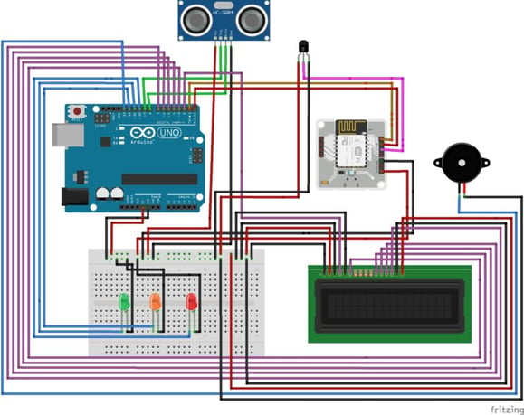
For Building this project we first configure the hardware connections. Then later on moving to the software part.
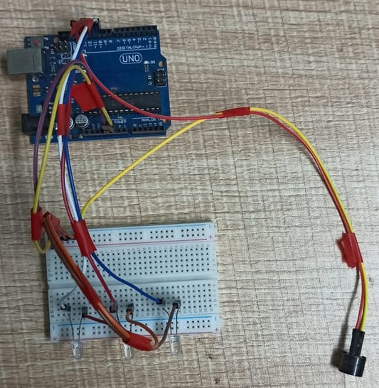
Step 1: Connecting 5v and GND of Arduino to the Breadboard for power connection to other components.
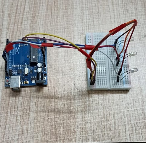
Step 2: Connecting LED’s
For Green LED:
- VCC of Green Colour LED to Digital Pin ‘10’ of the Arduino.
- GND of Green Colour LED to the GND of Arduino.
For Orange LED:
- VCC of Orange Colour LED to Digital Pin ‘11’ of the Arduino.
- GND of Orange Colour LED to the GND of Arduino.
For Red LED:
- VCC of Red Colour LED to Digital Pin ‘12’ of the Arduino.
- GND of Red Colour LED to the GND of Arduino.
Step 3: Connecting Buzzer
- VCC of Buzzer to Digital Pin ‘13’ of the Arduino.
- GND of Buzzer to the GND of Arduino.
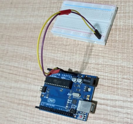
Step 4: Connecting HC-SR04 Ultrasonic Sensor
- VCC of Ultrasonic Sensor to 5v of Arduino.
- GND of Ultrasonic Sensor to GND of Arduino.
- Echo of Ultrasonic Sensor to Digital Pin ‘8’ of Arduino.
- Trig of Ultrasonic Sensor to Digital Pin ‘9’ of Arduino.
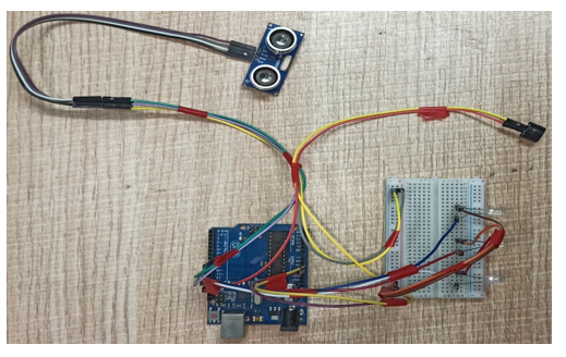
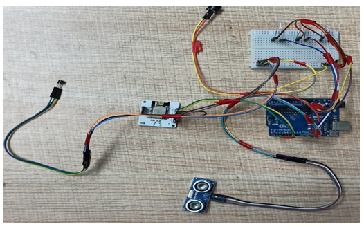
Step 5: Connecting Bolt WiFi Module
- 5v of Bolt WiFi Module to 5v of Arduino.
- GND of Bolt WiFi Module to GND of Arduino.
- TX of Bolt WiFi Module to RX of Arduino.
- RX of Bolt WiFi Module to TX of Arduino.
Step 6: Connecting LM35 Temperature Sensor
- VCC of LM35 to 5v of Bolt WiFi Module.
- Output Pin of LM35 to Pin ‘A0’ of Bolt WiFi Module.
- GND of LM35 to GND of Bolt WiFi Module.
Step 7:Connecting 16×2 LCD Display
- Pin 1,3,5,16 of 16×2 LCD to GND of Arduino.
- Pin 2,15 of 16×2 LCD to 5v of Arduino.
- Pin 4 of 16×2 LCD to Digital Pin ‘2’ of Arduino.
- Pin 6 of 16×2 LCD to Digital Pin ‘3’ of Arduino.
- Pin 11 of 16×2 LCD to Digital Pin ‘4’ of Arduino.
- Pin 12 of 16×2 LCD to Digital Pin ‘5’ of Arduino.
- Pin 13 of 16×2 LCD to Digital Pin ‘6’ of Arduino.
- Pin 14 of 16×2 LCD to Digital Pin ‘7’ of Arduino.
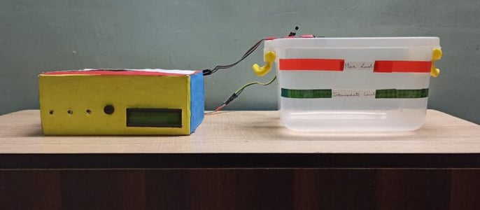
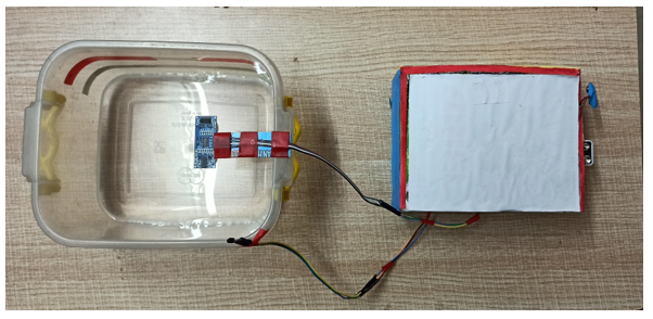
After doing the hardware connection put all the hardware components in one box.
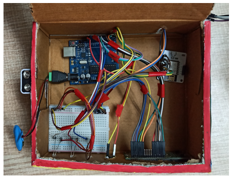
Also attach LM35 Temperature Sensor on the side of the container.
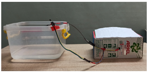
Also attach Ultrasonic sensor on the top of the container.
Software Programming
After the successful completion of hardware setup. Now it’s the time to do software setup for the project. For that you have to first Download and Install Arduino IDE and Python IDE from the link given above in the software apps and online services section. Also Creating account on various online app services and noting down the important keys and id’s. Below all the steps given to create account on online app services and noting down the keys.
Step 1:Creating an account on Twillo and setting up Twillo for sending Sms alerts.
- Visit https://www.twilio.com/ .
- Create account by clicking sign up, fill required details.
- Confirm your email.
- You will need to authenticate your phone number on which the sms alerts will be notified.
- Enter the code sent to your phone
- When prompted ” Do you write code?” Click yes
- Select python as your programming language
- When prompted “What is your target today? “Choose” Twilio as a project.
- When prompted “What do you want to do first? “Choose” Send or receive a message.
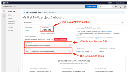
- My First Twilio Project Dashboard page will open. Now you can Edit your Project as “My Project”.
- Get a trial number and save it somewhere and then choose to use this number.
- You will see the ACCOUNT SID and AUTH TOKEN.
- We will need Account Sid, Auth Token and Trial Number of these so save them somewhere.
Step 2:Creating an account on Mailgun and setting up Mailgun for sending Email alerts.
- Visit https://www.mailgun.com/.
- Create an account by clicking on the start sending option and by filling up details.
- Verifying your Account.
- Once you have verified your Email after that you have add your phone number.
- After Entering your number. Click on send activation code. After some time you will receive one OTP. Enter the OTP. Click on Enter.
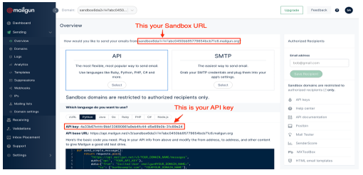
- After Creating account on Mailgun go to the overview option. Click on API and Click on Python.
- After doing this so you will receive API Key and Sandbox URL. Save this both credentials somewhere you will be further using in this project.
Step 4:Creating an account on Bolt Cloud and Bolt Android App and Link the Bolt Module to Cloud.
- Visit https://cloud.boltiot.com.
- Create account using Email-Id and password.(Use the same email which was used to order hardware kit also use same email for app for linking the hardware to cloud.)
- After creating account on cloud. Then Download Bolt Android App from playstore.
- Create a account on the Bolt app with the same email-Id then use the mobile hotspot for linking the Bolt WiFi module to cloud.
- After successful linking of the device to the cloud then go to the cloud website. The Bolt device will show the device as online.
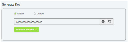
- Go to API section make the API as enable. Copy the API and save somewhere.
- Also copy the Bolt Device Id which is present on Bolt IoT dashboard and save it somewhere.
Bolt Device Id
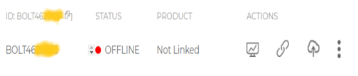
API Key
Step 5: Coding
After setting online app services and saving the keys somewhere. Now most important is to write code and allow sensors attached to microcontroller to take specific decisions.
Basically this project contains two editors to write the code. First is Arduino IDE in that we will write the arduino code. Second the Python IDE in that we will write the configuration file and the main code. Also the download link of both the editor can find above in the online app services section.
Step 5.1: Writing the code in the Arduino IDE
- Open the Arduino IDE(Downloaded from the above section).
- Click on new file. Choose the correct file path to save the file. Give appropirate name to the file and add .ino extention to the file and save the file.
- Now the core part of the project is writing code for Arduino Uno. Below this line complete code is given. You can refer the below code.
//IOT Based Flood Monitoring And Alerting System.
#include<LiquidCrystal.h>

LiquidCrystal lcd(2, 3, 4, 5, 6, 7);

const int in = 8;
const int out = 9;
const int green = 10;
const int orange = 11;
const int red = 12;
const int buzz = 13;

void setup() {
Serial.begin(9600);
lcd.begin(16, 2);
pinMode( in , INPUT);
pinMode(out, OUTPUT);
pinMode(green, OUTPUT);
pinMode(orange, OUTPUT);
pinMode(red, OUTPUT);
pinMode(buzz, OUTPUT);
digitalWrite(green, LOW);
digitalWrite(orange, LOW);
digitalWrite(red, LOW);
digitalWrite(buzz, LOW);
lcd.setCursor(0, 0);
lcd.print("Flood Monitoring");
lcd.setCursor(0, 1);
lcd.print("Alerting System");
delay(5000);
lcd.clear();
}

void loop() {
long dur;
long dist;
long per;
digitalWrite(out, LOW);
delayMicroseconds(2);
digitalWrite(out, HIGH);
delayMicroseconds(10);
digitalWrite(out, LOW);
dur = pulseIn( in , HIGH);
dist = (dur * 0.034) / 2;
per = map(dist, 10.5, 2, 0, 100);
#map
function is used to convert the distance into percentage.
if(per < 0) {
per = 0;
}
if (per > 100) {
per = 100;
}
Serial.println(String(per));
lcd.setCursor(0, 0);
lcd.print("Water Level:");
lcd.print(String(per));
lcd.print("% ");
if (per >= 80) #MAX Level of Water--Red Alert!{
lcd.setCursor(0, 1);
lcd.print("Red Alert! ");
digitalWrite(red, HIGH);
digitalWrite(green, LOW);
digitalWrite(orange, LOW);
digitalWrite(buzz, HIGH);
delay(2000);
digitalWrite(buzz, LOW);
delay(2000);
digitalWrite(buzz, HIGH);
delay(2000);
digitalWrite(buzz, LOW);
delay(2000);

}
else if (per >= 55) #Intermedite Level of Water--Orange Alert!{
lcd.setCursor(0, 1);
lcd.print("Orange Alert! ");
digitalWrite(orange, HIGH);
digitalWrite(red, LOW);
digitalWrite(green, LOW);
digitalWrite(buzz, HIGH);
delay(3000);
digitalWrite(buzz, LOW);
delay(3000);

}
else #MIN / NORMAL level of Water--Green Alert!{
lcd.setCursor(0, 1);
lcd.print("Green Alert! ");
digitalWrite(green, HIGH);
digitalWrite(orange, LOW);
digitalWrite(red, LOW);
digitalWrite(buzz, LOW);
}

delay(15000);
}
- After writing the code. Verify the code and then upload the code to the specific Arduino using USB Cable type A. Remember while uploading select specific board you want to upload.
Step 5.2: Writing the code in Python IDE.
- For writing python code we will be using python IDE.
- In this project we will be making two python files. One will be saved in the name of conf.py and other will be main.py.
- The purpose of making two files is to make the code understandable. Also this both python files will be usefull in sending sms and emails alerts to users.
- Now the most important part is arrived writing code in Python IDE. The full code is divided into two parts. The detailed code is given below.
- Open Python 3.7 IDE(Downloaded from the above section).
- Click on new file. Save the file in the name conf.py.
- conf.py: The file consists of important Api keys, Device id of Bolt IoT WiFi Module. Also it consists of important keys of Twillo and Mailgun respectively which will be further usefull in this project.
- Below is the complete structure of conf.py file. Make sure that you add the updated Bolt API key, device id and Mailgun and Twillo details respectively:
#twillo details for sending alert sms
SID = 'You can find SID in your Twilio Dashboard'
AUTH_TOKEN = 'You can find  on your Twilio Dashboard'
FROM_NUMBER = 'This is the no. generated by Twilio. You can find this on your Twilio Dashboard'
TO_NUMBER = 'This is your number. Make sure you are adding +91 in beginning'

#bolt iot details
API_KEY = 'XXXXXXXXX'
   #This is your Bolt cloud API
Key.
DEVICE_ID = 'BOLTXXXXXXXXX' #This is the ID of your Bolt device.

#mailgun details for sending alert E-mails
MAILGUN_API_KEY = 'This is the private API key which you can find on your Mailgun Dashboard'
SANDBOX_URL= 'You can find this on your Mailgun Dashboard'
SENDER_EMAIL = 'test@ + SANDBOX_URL' # No need to modify this. The sandbox URL is of the format test@YOUR_SANDBOX_URL
RECIPIENT_EMAIL = 'Enter your Email ID Here'
- After writing the conf.py now the last part is to write the main.py code. This code will be helpfull to send sms and email alerts when the water level crosses the threshold.
- Open the Python IDE.
- Click on new file. Save the file in the name main.py. Save the file in the same path where conf.py is saved.
- main.py: This file consists of the main coding facility. Discussed earlier it will be used to send sms and emails alerts. It will be also helpfull to keep close monitor on water level to send alerts whenever required.
- Below is the complete code of main.py.
import conf
from boltiot import Sms, Email, Bolt
import json, time
intermediate_value = 55
max_value = 80
mybolt = Bolt(conf.API_KEY, conf.DEVICE_ID)
sms = Sms(conf.SID, conf.AUTH_TOKEN, conf.TO_NUMBER, conf.FROM_NUMBER)
mailer = Email(conf.MAILGUN_API_KEY, conf.SANDBOX_URL, conf.SENDER_EMAIL, conf.RECIPIENT_EMAIL)
def twillo_message(message):
try:
print("Making request to Twilio to send a SMS")
response = sms.send_sms(message)
print("Response received from Twilio is: " + str(response))
print("Status of SMS at Twilio is :" + str(response.status))
except Exception as e:
print("Below are the details")
print(e)
def mailgun_message(head,message_1):
try:
print("Making request to Mailgun to send an email")
response = mailer.send_email(head,message_1)
print("Response received from Mailgun is: " + response.text)
except Exception as e:
print("Below are the details")
print(e)
while True:
print ("Reading Water-Level Value")
response_1 = mybolt.serialRead('10')
response = mybolt.analogRead('A0')
data_1 = json.loads(response_1)
data = json.loads(response)
Water_level = data_1['value'].rstrip()
print("Water Level value is: " + str(Water_level) + "%")
sensor_value = int(data['value'])
temp = (100*sensor_value)/1024
temp_value = round(temp,2)
print("Temperature is: " + str(temp_value) + "°C")
try:
if int(Water_level) >= intermediate_value:
message ="Orange Alert!. Water level is increased by " +str(Water_level) + "% at your place. Please be Safe. The current Temperature is " + str(temp_value) + "°C."
head="Orange Alert"
message_1="Water level is increased by " + str(Water_level) + "% at your place. Please be Safe. The current Temperature is " + str(temp_value) + "°C."
twillo_message(message)
mailgun_message(head,message_1)
if int(Water_level) >= max_value:
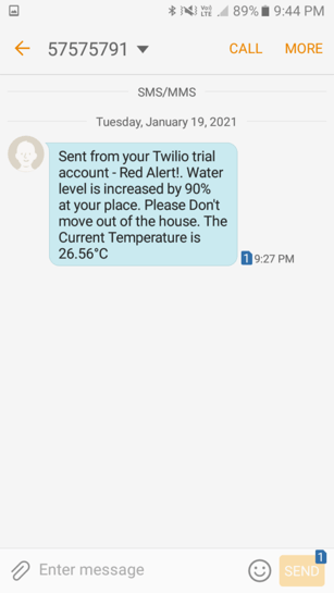
message ="Red Alert!. Water level is increased by " + str(Water_level) + "% at your place. Please Don't move out of the house. The Current Temperature is " + str(temp_value) + "°C"
head="Red Alert!"
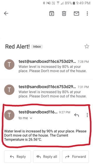
message_1="Water level is increased by " + str(Water_level) + "% at your place. Please Don't move out of the house. The Current Temperature is " + str(temp_value) + "°C."
twillo_message(message)
mailgun_message(head,message_1)
except Exception as e:
print ("Error occured: Below are the details")
print (e)
time.sleep(15)
After Successfully writing code for Arduino and Python. Now it is the time to test and demonstrate the project. Move to next section for demonstration of the project.
Demonstration
Lets First have a look at the workflow of this project.
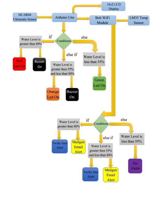
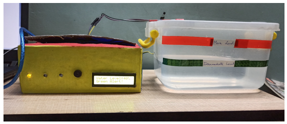
For doing the practical demonstration. First connect the USB cable type-B to the Laptop’s USB slot for power supply. Also simultaneously run the python program(i.e Main.py). Firstly the ultrasonic sensor will sense the water level in distance and then the arduino program will help to convert it into percentage. Also the sensed water level will be displayed on Lcd display(In Percentage) along with zone/area the water level is present. The full water tank/container is divided into 3 zones i.e Green, Orange and Red. Now lets look into each zone.
- When water level is at Min/Normal level. That resembles ‘Green Alert’. This means that water is at normal position and no sign about flood condition. Also green led will glow and it will also show green alert in Lcd display with water level.
- When water level crosses the Intermediate level. That resembles ‘Orange Alert’. This means that water has crossed the 55% mark and there can be chances of flood condition at that place. With increase in water level the system sends Sms and Email alerts to the authority or registered user from Twillo and Mailgun Services respectively. Also orange led will glow and buzzer will buzz. It will also show orange alert in Lcd display.
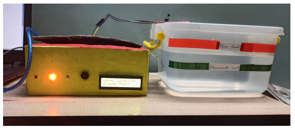
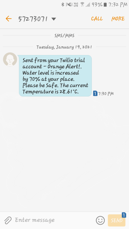
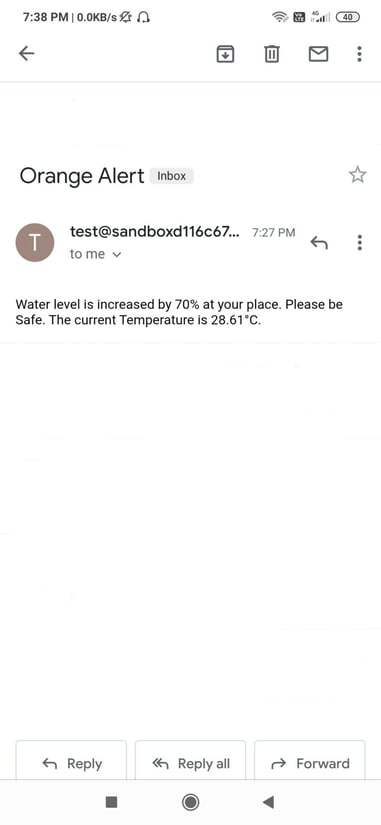
Also Sms and Email is send to registered user with proper message and current temperature of that place.
Twillo Sms Alert:
Mailgun Email Alert
- When water level crosses the Max Level. That resembles ‘Red Alert’. This means that water level has crossed the 80% and flood situation has occured at that place. With increase in water level the system sends Sms and Email alerts to the authority or registered user from Twillo and Mailgun Services respectively. Also red led will glow and buzzer will buzz for two times. It will also show red alert in Lcd display.
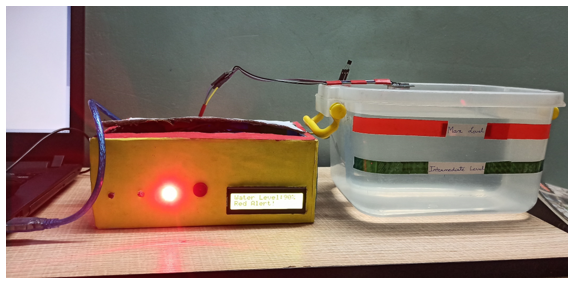
Also Sms and Email is send to registered user with proper message and current temperature of that place.
The Video Demonstration
Watch our project in action:
Schematics Diagram
Conclusion
Nowadays the Internet Of things (IoT) is broadly used in worldwide, this system will display the data of the water level measured on lcd display. This project can be very helpful to the Meteorological Department to continuously monitor the dams and river beds water level. With this project it can save many people lives by giving alerts when the water level crosses beyond the limit. This project is very cost-effective, flexible and productive in areas where flood conditions happens everytime
Want to build more such IoT and ML projects? Want to learn IoT and ML from basics?
Check out the Bolt IoT and ML training. This online video training is excellent for those who want to start with IoT and ML because it teaches you to build projects from the basics. Click on the button below to know more about the training.