Smart Door with Face Unlock using Bolt IoT

Welcome, curious pal! We live in an internet revolutionized era where it is now easier than ever to experiment and innovate ourselves to come up with brilliant ideas that can have a positive impact on millions around the world.
Ever wanted to add a little bit of extra security to your shelf, drawers, wardrobes or doors at home? When it comes to innovation using internet, among thousands of platforms and tools available to us, a couple that stand out are Arduino and Bolt IoT. In this project, we'll modify a standard shelf to have a security system that unlocks using Face Verification. We'll build a Windows Forms Application in C# that can store, verify and unlock trusted faces. It uses FacePlusPlus API for face verification and Bolt IoT Cloud API for communicating with Bolt WiFi Module and Arduino. We'll interface Bolt WiFi Module with an Arduino Uno, that'll control a servo motor to lock/unlock the door.
Excited? Let's get started.
Things used in this project
Hardware components -
- Bolt WiFi Module
- Arduino Uno R3
- Servo motor
- Hot glue gun
- Cardboard box
- Pair of scissors
Software components -
- Bolt Cloud
- Bolt IoT android App
Software Programming
Step 1: Building the Software
We'll build a Windows Forms Application using Visual Studio. This application runs on a Windows machine, and will be responsible for managing authorized faces, verifying a face using FacePlusPlus API and communicating with the Bolt WiFi Module. We'll be using C# to code.
Fire up Visual Studio and create new Windows Forms Application project. If you are completely new to Visual Studio, I recommend to learn the basics of Windows Forms Application Development using Visual Studio. This and this are good resources to get started.
In this tutorial, I'll only be explaining code using snippets from the project that does main and important functions. It'll be tedious and unnecessary to go through the entire code as most of it is self explanatory and well documented.
Our Visual Studio project makes use of 3 libraries for various purposes. They are:
- AForge .NET: A popular .NET framework used for image processing in Windows. We use it for capturing images from a webcam.
- Bolt IoT API .NET: An unofficial client library that I wrote in C#, for communicating the Bolt Cloud API.
- Newtonsoft JSON: A popular high-performance JSON framework for .NET. Used for parsing API responses in our project.
NOTE: For clarity in usages of different methods in the above APIs, please refer to their respective documentations here, here and here.
Step 2: Getting API credentials
1. Bolt Cloud API Credentials
If you haven't already, to to cloud.boltiot.com and set up an account. Once you're logged in, link your WiFi Module with the Bolt Cloud. For that, download the Bolt IoT Setup App on your mobile phone. Follow the instructions given in the app to link your device with your account. This involves pairing the Bolt with local WiFi network. Once successfully linked, your dashboard will display your device. You can now get your Device ID and and API Key from the dashboard.
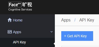
2. FacePlusPlus API Credentials
Another API service that we rely on in this project is FacePlusPlus API. It's a free platform that offers various kinds of image recognition services. We use it for facial identification. Create an account and go to the FacePlusPlus console. Go to API Key under Apps and click on +Get API Key. Note down the newly generated API Key and API Secret.
Now you should have the following ready:
private readonly string BOLT_DEVICE_ID = "BOLTXXXXXX";
private readonly string BOLT_API_KEY = "XXXXXXXX...";

private readonly string FPP_API_KEY = "XXXXXXXX...";
private readonly string FPP_API_SECRET = "XXXXXX...";
We create a new global instance of the Bolt class called myBolt, through which we'll do all the future communications with the WiFi Module:
myBolt = new Bolt(BOLT_API_KEY, BOLT_DEVICE_ID);
That said, now let's see how our application performs some of the core functions.
Step 3: Lock/Unlock Door
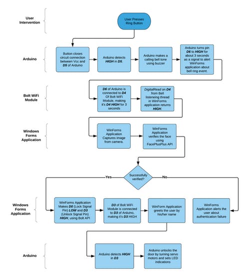
We have designed the circuit such that when Digital Pin 0 is HIGH, the door is supposed to get locked, and when Digital Pin 3 is HIGH, door's supposed to be unlocked. This'll be made more clear later when we discuss the circuit schematics.
For locking, we use the DigitalMultiWrite method from library to write HIGH value to D0 and LOW value to D3. This will signal the Arduino to lock the door. Similarly for unlocking, we'll write LOW value to D0 and HIGH value to D3. This will signal the Arduino to unlock the door. We'll discuss the Arduino code and circuit design later in this tutorial.
Code that performs locking:
private async Task LockDoor()
{
 MultiPinConfig multiPinConfig = new MultiPinConfig();
 MultiPinConfig.AddPinState(DigitalPins.D0,   DigitalStates.High); //Lock Signal
 multiPinConfig.AddPinState(DigitalPins.D3,   DigitalStates.Low); //Unlock Signal

 await myBolt.DigitalMultiWrite(multiPinConfig);

 multiPinConfig = new MultiPinConfig();
 multiPinConfig.AddPinState(DigitalPins.D0,   DigitalStates.Low); //Lock Signal
 multiPinConfig.AddPinState(DigitalPins.D3,   DigitalStates.Low); //Unlock Signal

   await myBolt.DigitalMultiWrite(multiPinConfig);
}
Code that performs unlocking:
private async Task UnlockDoor()
{
 MultiPinConfig multiPinConfig = new MultiPinConfig();
 multiPinConfig.AddPinState(DigitalPins.D0,   DigitalStates.Low); //Lock Signal
 multiPinConfig.AddPinState(DigitalPins.D3,   DigitalStates.High); //Unlock Signal

 await myBolt.DigitalMultiWrite(multiPinConfig);

 multiPinConfig = new MultiPinConfig();
 multiPinConfig.AddPinState(DigitalPins.D0,   DigitalStates.Low); //Lock Signal
 multiPinConfig.AddPinState(DigitalPins.D3,   DigitalStates.Low); //Unlock Signal

 await myBolt.DigitalMultiWrite(multiPinConfig);
}
Step 4: Lock/Unlock Door
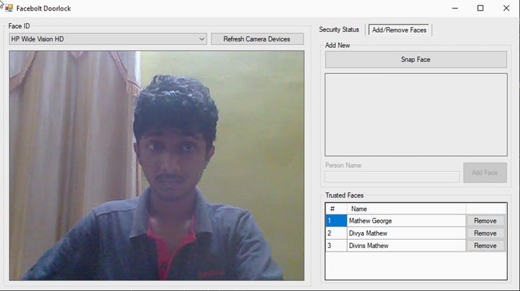
The trusted face's image data is encoded into a Base64 string and is stored locally in the machine. A list of corresponding names of each face is also stored. In our program, to add a face, we first verify if there is a face available in the current frame. We do this using the Detect API of FacePlusPlus. It returns a JSON response that will contain features of the detected face. If no face is detected the response will simply be []. Once a face is detected, we save the image's base64 encoded string and corresponding name. Here's a video demo of adding a trusted face.
Removing a face is pretty straight forward. Pressing the remove button will delete the image data and name from the saved list.
Code that adds and saves the face information:
//Converting image to base64 string and adding it to the list.
ImageDataList.Add(ImageToBase64((Image)PreviewBox.Image.Clone()));
//Adding name of the face to the list
NameList.Add(FaceNameTextBox.Text.Trim());

//Saves the face image data as a base encoded string, along with its name
Properties.Settings.Default.Base64ImageData = ImageDataList;
Properties.Settings.Default.FaceNames = NameList;
Properties.Settings.Default.Save();
Code that removes a face information:
//Removing face information at specified position in the list
NameList.RemoveAt(e.RowIndex);
ImageDataList.RemoveAt(e.RowIndex);

//Saving the the list after removal of a face
Properties.Settings.Default.FaceNames = NameList;
Properties.Settings.Default.Base64ImageData = ImageDataList;
Properties.Settings.Default.Save();
Check out the code in the attached project where the process is explained as comments in each line for having a clear idea.
Step 5: Face Verification
We verify if a face is trusted or not by using the Compare API in FacePlusPlus. During this process, we linearly iterate through each face in the saved list and compare it with the captured image. If the API returns a confidence of more than 80%, we'll unlock the door.
The code that does this comparison looks something like this:
WebClient client = new WebClient();

byte[] response = client.UploadValues
                         ("https://api-us.faceplusplus.com/facepp/v3/compare",
                          new NameValueCollection()
{
    { "api_key", FPP_API_KEY },
    { "api_secret", FPP_API_SECRET },
    { "image_base64_1", face1Base64},
    { "image_base64_2", face2Base64}
    });
});

string confidence = JObject.Parse(System.Text.Encoding.UTF8.GetString(response))
                                 ["confidence"].ToString();
WebClient.UploadValues method sends the request to FacePlusPlus API along with the base64 encoded face data of two faces to be compared and our API credentials. The response is parsed using Newtonsoft JSON library and confidence value is obtained. Read the Compare API documentation for understanding the arguments clearly.
Step 6: The Bell Listening Thread
We plan to provide a physical push button, something like a calling bell button, so that the user can press while looking at the camera to unlock the door. To make this possible, we need to create a new dedicated thread that continuously listen for bell button press event.
Later in this tutorial, we'll see how push button is employed and how it will make D4 pin of Bolt WiFi module HIGH when the button is pressed. For now, we'll just assume the above. So in this thread, we continuously DigitalRead the value of D4 pin. If it's HIGH, we'll take that as bell ring event and do the face capture and verification.
Here's the code that'll run continuously on the bell listening thread:
while (ListenForBell)
{
    Response R = await myBolt.DigitalRead(DigitalPins.D4);
    if (R.Value == "1")
    {
        RingBell_Click(null, null);
        Thread.Sleep(2000);
    }
    Thread.Sleep(2000);
}
We stop and wait for 2 seconds between each iteration. Otherwise it'll exhaust Bolt Cloud API's usage quota quickly.
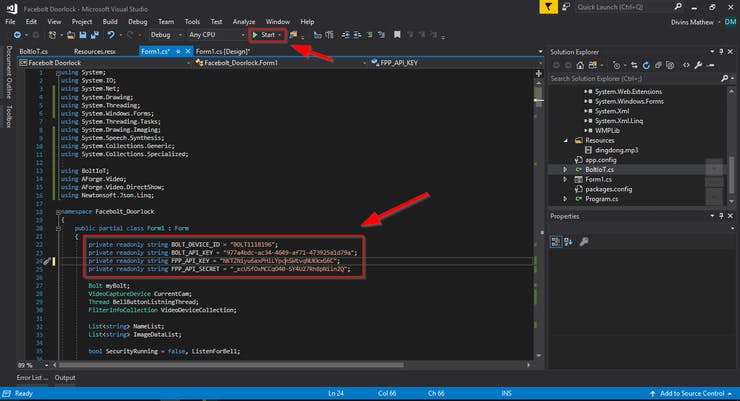
Step 7: Building The Visual Studio Project
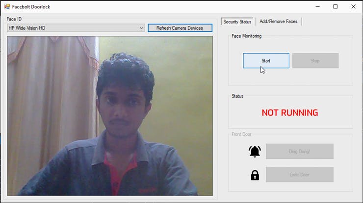
Download the entire project here. Open the Facebolt Doorlock.sln file in Visual Studio. After the solution loads, open Form1.cs file and update the code with your API credentials. Press the green play button named 'Start', to build and run the program.
The program lets you select from camera devices attached to the system and see a live feed from the camera. You can Add/Remove a trusted face. Start face monitoring. Once the program verifies the connectivity of your Bolt Device, you can ring the bell or lock the door directly from the program.
It's ok if you're now confused on how the face verification, locking and unlocking works in the program. It'll become more clear once we see the circuit schematic design and Arduino code. I'll also break down the flow of events of each operation at the end.
Hardware Setup
Step 1: Circuit Design and Arduino Code
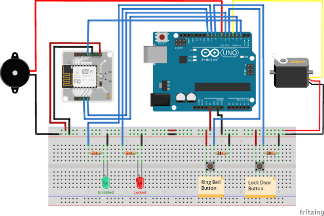
In our circuit, we intend to implement the following features:
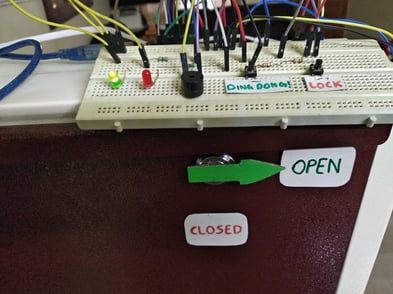
- Red and Green LED indication for locked and unlocked door states, respectively.
- A push button to act like a calling bell switch. When pressed, our WinForms application should verify face and open door upon successful face authentication.
- Another push button to lock the door.
- A buzzer that beeps in the event of a doorbell ring and door lock
The circuit connection of our project is shown below:
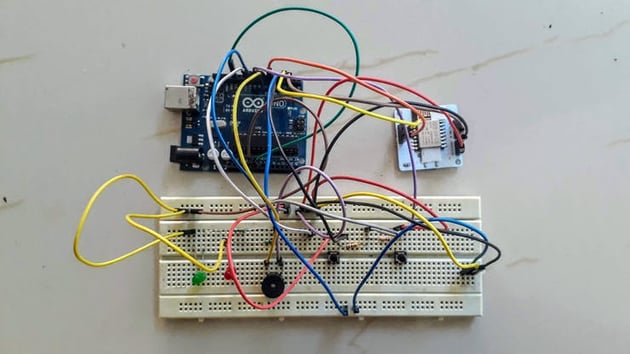
If you haven't already, download the Arduino IDE from here and connect your Arduino to the system. Make sure you've set the right Arduino model and Port in the IDE settings, before uploading the code.
Step 2: Write Arduino code
#include <Servo.h>

#define ServoPin 4
#define LockSignalPin 2
#define UnLockSignalPin 3
#define BellButtonPin 5
#define LockButtonPin 8
#define RingBellSignalPin 6
#define BuzzerPin 7
#define GreenLedPin 9
#define RedLedPin 10

Servo myServo;

void setup()
{
    pinMode(LockSignalPin, INPUT);
    pinMode(UnLockSignalPin, INPUT);
    pinMode(BellButtonPin, INPUT);
    pinMode(LockButtonPin, INPUT);

    pinMode(BuzzerPin, OUTPUT);
    pinMode(RedLedPin, OUTPUT);
    pinMode(GreenLedPin, OUTPUT);
    pinMode(RingBellSignalPin, OUTPUT);

    digitalWrite(RedLedPin, LOW);
    digitalWrite(GreenLedPin, LOW);
    digitalWrite(RingBellSignalPin, LOW);

    myServo.attach(ServoPin);
    Serial.begin(9600);
}

void loop()
{
    int lockButton, lock, unlock, bell;
    char snum[5];

    lock = digitalRead(LockSignalPin);
    unlock = digitalRead(UnLockSignalPin);

    // Check if lock signal from Bolt is HIGH
    if(lock == HIGH)
    {
        // Turn motor to locked position
        myServo.write(120);

        // Set LED indications
        digitalWrite(GreenLedPin, LOW);
        digitalWrite(RedLedPin, HIGH);

        // Buzz locking sound
        digitalWrite(BuzzerPin, HIGH);
        delay(1000);
        digitalWrite(BuzzerPin, LOW);
        delay(1000);
    }
    // Check if unlock signal from Bolt is HIGH
    else if(unlock == HIGH)
    {
        // Turn motor to unlocked position
        myServo.write(0);

        // Set LED indications
        digitalWrite(GreenLedPin, HIGH);
        digitalWrite(RedLedPin, LOW);
        delay(2000);
    }

    bell = digitalRead(BellButtonPin);
    if(bell == HIGH) // User pressed bell ring betton
    {
        // Signal Bolt that ring button was pressed
        digitalWrite(RingBellSignalPin, HIGH);

        // A calling bell sound pattern !
        digitalWrite(BuzzerPin, HIGH);
        delay(100);
        digitalWrite(BuzzerPin, LOW);
        delay(20);
        digitalWrite(BuzzerPin, HIGH);
        delay(200);
        digitalWrite(BuzzerPin, LOW);
        delay(100);
        digitalWrite(BuzzerPin, HIGH);
        delay(100);
        digitalWrite(BuzzerPin, LOW);
        delay(20);
        digitalWrite(BuzzerPin, HIGH);
        delay(200);
        digitalWrite(BuzzerPin, LOW);
        delay(1500);

        // Turn off the signal
        digitalWrite(RingBellSignalPin, LOW);
    }

    lockButton = digitalRead(LockButtonPin);
    if(lockButton == HIGH) // User pressed lock betton
    {
        // Turn motor to locked position
        myServo.write(120);

        // Set LED indications
        digitalWrite(GreenLedPin, LOW);
        digitalWrite(RedLedPin, HIGH);

        // Buzz locking sound
        digitalWrite(BuzzerPin, HIGH);
        delay(1000);
        digitalWrite(BuzzerPin, LOW);
    }
}
Step 3: Event Flows
Now that we have both the WinForm application and the Arduino design ready, let's dive into the code and explore the control flow of each operation.
1. Ring Button Press
2. Lock Button Press
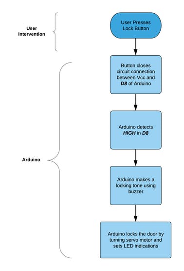
Both the above operations can also be executed directly from the Windows Forms Application as well.
Here, we can observe that the Bolt WiFi Module serves as an important wireless interface between the Windows Forms Application and the Arduino. Usage of Bolt Cloud API allows us to extend our project and build applications on other platforms like Android and unlock the door using our phones! This flexibility is the power of IoT and the Bolt Platform.
Now that we've completed the software design part, lets go ahead and build a lockable door mechanism.
Step 4: Building The Hardware
I have a shoe rack lying around so in this project, I'm gonna use it for lock demonstration. You can use a shelf or a door or a wardrobe or anything that has a hackable locking mechanism. It's really up to you.
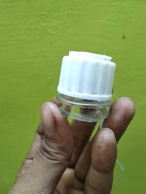
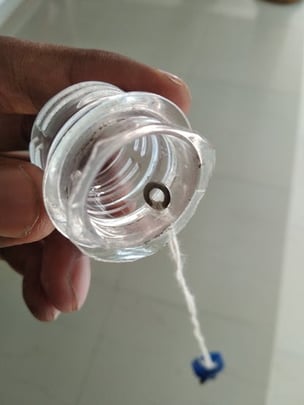
We need to build a coupling mechanism that connects our servo motor with the lock. For this, my idea is to use a cut-off neck from a bottle and another bottle's cap. Attach the bottle neck to the servo motor and the cap to the lock. We'll then couple them using a nylon thread. This will result in the lock/unlock action whenever the motor turns.
The required bottle neck with a hole drilled on it's cap looks something like shown below. We'll be attaching this to the shoe rack's locking shaft.
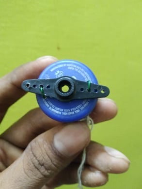
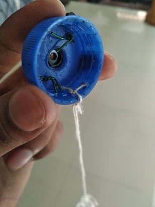
Another bottle's cap has to be attached to the servo motor. We use copper wires to connect cap to the turning shaft of the motor.
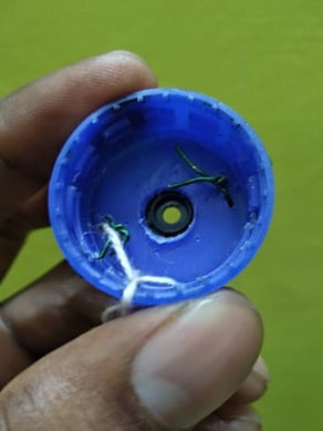
Now we need to couple these two. For that we use nylon thread. Make a loop using the thread with required length and attach thread to both the caps.
Once coupled, they can cause a mutual rotating action:
Now that we have our turning mechanism ready, it's time to hack into the lock and fix our bottle neck in it. We had drilled a hole in it, so all we need to do is unscrew the locking shaft from the rack, place the bottle neck above it and re-screw the lock back tight.
Now the only thing left to do is to fix the servo motor to the shoe rack. We'll use a hot glue gun to seal the motor to the rack.
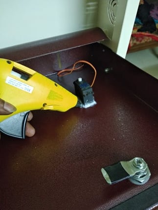
After adjusting the thread's length and sufficiently tightening it, we have our final set up ready. As seen below, servo motor can correctly lock and unlock the door!
You don't necessarily have to use the bottle neck - thread method of coupling. Use whatever method that's most suitable and convenient with your lock system.
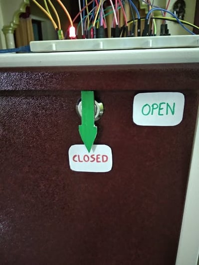
Luckily, I had a small opening at the right place in the rack. this allowed me to get the servo motor connections out easily. After a little decoration work and labeling, our final smart shoe rack is now ready for action.
We're all set now. All that's left to do is fire up the circuit, add a trusted face on the WinForms application and enjoy the face lock security on our doors. You'll need to power both the Arduino and Bolt WiFi Module. I use a 10000 mAh power bank to power them both. The WebCam I use is a Microsoft LifeCam VX-800. It's old but still better than the laptop's camera. Do check out the demonstration video. It shows the working of our project in detail.
The Video Demonstration
Watch our project in action (Apologies for the video quality):
Conclusion
Huff.. that was pretty long. This project is fruit of Internshala's IoT training, powered by Bolt IoT. Although this project is pretty simple, it show us the potential of Internet of Things and how it can make people's daily life easier.
Anyways.. This was a great learning experience for me. I hope you guys will enjoy building this and I'm excited to see what new innovations you'll come up with. I'm concluding by expressing my sincere thanks to the Training team at Internshala and Bolt IoT for making this venture possible.
And that's a wrap!
Want to build more such IoT and ML projects? Want to learn IoT and ML from basics?
Check out the Bolt IoT and ML training. This online video training is excellent for those who want to start with IoT and ML because it teaches you to build projects from the basics. Click on the button below to know more about the training.