
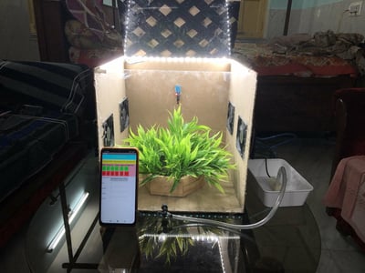
Appliances used in green houses for growing different plants such as the water-pump, heater, cooling fans, Led-lights and the most unique part about this this project is that it has a retractable roof. The system is developed with two modes, and the appliances can be controlled from an app that is also self-made which can make the most of the greenhouse operator to grow the plants more safely without facing any type of fussy situation.
Excited? Let's get started.
Things used in this project
Hardware components -
- Arduino Uno
- Bolt-Iot wifi module
- 8 channel relay module
- LDR
- 100 ohm ressistance
- Servo
- Led stips
- 4xCPU cooling Fans
- 32 AWG nichrome wire
- Female barrel jack adapter
- 2xTap switches
- mini 12v water pump with pipe
- sprinter
- Dht11 temperature and humidity sensor
- moisture sensor
- Serial converter (for power supply to the servo and relay module)
- Some cardboard for making the model.
- Jumper wires
- Cable for arduino and BOLT 20.
- small plant-pot
Software components -
- Arduino IDE
- Bolt IoT android App
- MIT APP Inventory
Hardware Setup
Step 1:Introduction
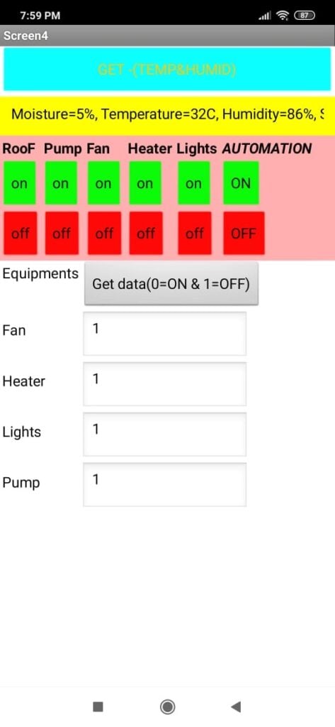
This project has specially two modes – 1. The manual mode and 2. The autonomous mode, now the manual mode is the defalt mode where the system hears the command given to it by the user to controll the lights,fans,water-pump and the roof. This manual controlling is done by the user throught the app , made by the MIT app inventory containing 5 different switches for the different equipments and including the switch to turn on and off the autonomous mode.
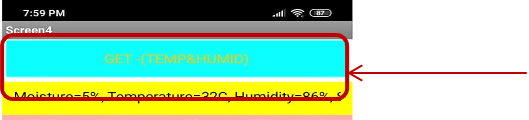
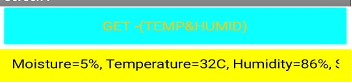
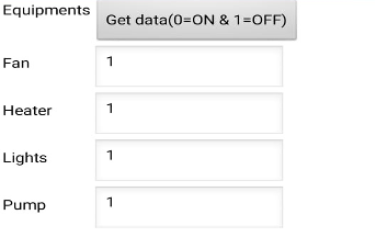
Now the app also contains two display sections, First and in the top most there we can see the text box where we can get the temperature,sunlight,moisture and humidity of the greenhouse by clicking on the “get” button on the app.Secondly there we can see the column where the app will display which of theutensils are ON or OFF by displaying 0 and 1, where 0-means ON and 1-means OFF,by taping the “get data ” button
Now, the sunlight is measured with a own made ldr sensor with a 100 ohm ressistance which gives a analog output to the arduino depending upon the brightness of the sunlight. Morever the heater have been made from the nichome wire by giving 12v across the wire.This wire is actually used for foam cutting but can also produce sufficient amount of heat when 12v is given across the terminals.
Step 2: Demonstration - AUTOMATIC CONTROLLING (MODE-1)
This is the mode where the system takes care of every little thing, when the lights, pump, fans, heater and even the roof has to be putted off or on depending upon the circumstances of the greenhouse, calculated by the system by collecting the data of the different sensors attached to it.
AUTOMATIC CONTROLLING OF THE COOLING-FANS
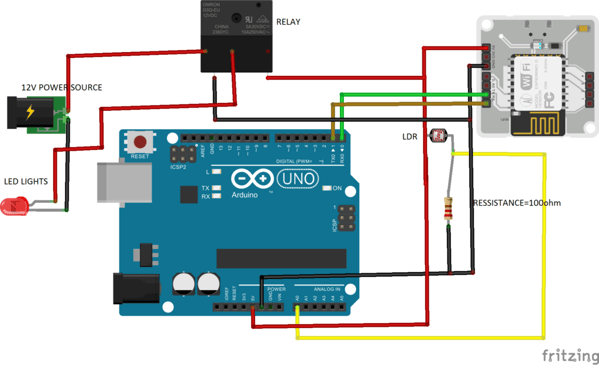
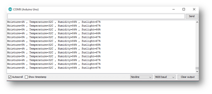
When the Circuit is connected as of the above connection the output will be given in a range of 0-1024 as the analog output depending upon the brightness of the sun, now the brightness is calculated in the given formula= (sensor value/1024)*100, here we can get the percentage of brightness as output and when the brightness goes below 40% the system automatically switch on the LED light by putting the relay as high. During this automation mode the ledCannot be switched off from the mobile app, for doing so, it has to be again put into manual mode by turning off the automation mode.
AUTOMATIC CONTROLLING OF THE FAN
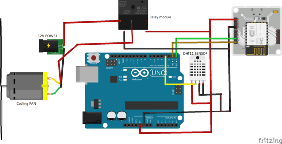
When the Circuit is connected as of the above connection and after installing the Adafrutit libraries for dht11, the output of the temperature and the humidity will be given, Now after initializing the data from the sensor the system will analyze it and if the temperature is above 32 degree C or the Humidity is above 85% then the system will automatically turn on the cooling fan unless the temperature or the humidity comes again to the moderate conditions for maintaining a comfortable and likely condition for the plants to grow well without getting damaged due to the overheating.
Automatic controlling of the water pump
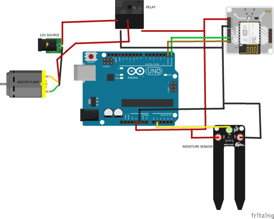
When the Circuit is connected as of the above connection the output will be given in a range of 0-1024 as the analog output depending upon the moisture present in the soil, now the moisture% is calculated in the given formula= (sensor value/1024)*100, here we can get the percentage of moisture as output and when the moisture goes below 40% the system automatically switch on the water-pump by putting the relay as high, until the moisture goes above 40%,for spreading the water throughout the soil a sprinkler had also been attached to the pipe for spreading the water equally to each and every plants.
Automatic controlling of the heater
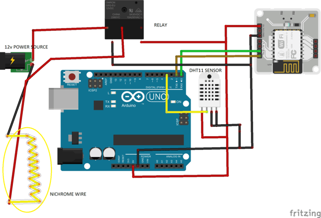
When the Circuit is connected as of the above connection and after installing the Adafrutit libraries for dht11, the output of the temperature and the humidity will be given, Now after initializing the data from the sensor the system will analyze it and if the temperature is below 29 degree C then the system will automatically turn on the heater unless the temperature or the room temperature comes again to the moderate conditions for maintaining a comfortable and likely condition for the plants to grow well without getting damaged due to too cooling temperature.
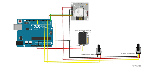
Automatic controlling of the retractable-roof
Now coming to the most unique part of the project, the retractable-roof,
Many questions may arise what if the roof is fixed in an open position;
- The plant may get destroyed in a particular day when the sun is too bright.
- The plant may get destroyed due to the overcooling in a cold winter day.
- The plant may also get destroyed from over-watering during the rainy days.
- If the roof is fixed to closing position then also the room will be overheated since the glass only absorbs the heat and will not let it go and it will be difficult for the cooling system to cool the room for the long period of time.
Now for all this cons, I had given a retractable roof to this project, the roof can do the following task,
- When the system detects the sunlight over 80% then the roof will automatically be closed by the system.
- When the temperature goes bellow a threshold point the roof will also get automatically closed when the system sense the temperature going below the threshold point which can be harmful for the plant by closing the roof, so that the heat may remain in the room for longer period of time.
- In the system we had given command to the system to put the water-pump automatically off when the moisture of the soil goes above 40%, now we had also given command to the system to close he roof when the moisture is above 60%.Here comes the tricky part, when the moisture actually goes above 60% the system first checks if the pump is off or not if by any chance it is ON then it will turn it on but if it is already off then it will assume that rain is happening since there could not be any reason for increasing the soil moisture this way. When it detects so, it will close the roof to save the plants from getting extra water which it does not needed.
- Coming to the point that the plant also need fresh air and also have to save the room from getting overheated during the day time, my system will actually check whether the brightness of the sun is less than 65%, the temperature of the room is above 29 degree C and the moisture is below 50%, if all the conditions are satisfied at a time then it will open the roof automatically.
Step 2: MANUAL CONTROLLING (MODE-2)
This is the default mode of the system, where the system only hear the command(s) given to it as of in the automatic mode it will not hear any command given to it if by chance the user puts the lights ON in the day time it will not hear the command and it will overlook to the command. Now, to make the system to hear the user’s command, the automation mode has to be put to off.
This switches from the App actually controls the above mentioned appliances in the manual mode.
This switch from the App actually gets the data from the Arduino from the UART to display the sensor’s value to the app.
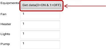
This switch from the App actually checks which of the appliances are ON or OFF by reading the digital pins of the Bolt-Iot which is then further connected to the relay module.
Software Programming
Step 1: App Making

- First go to this site, https://appinventor.mit.edu/.
- Then go to the, “Create app” on the upper left part.
- After that sign in through Google-account, then create a project.
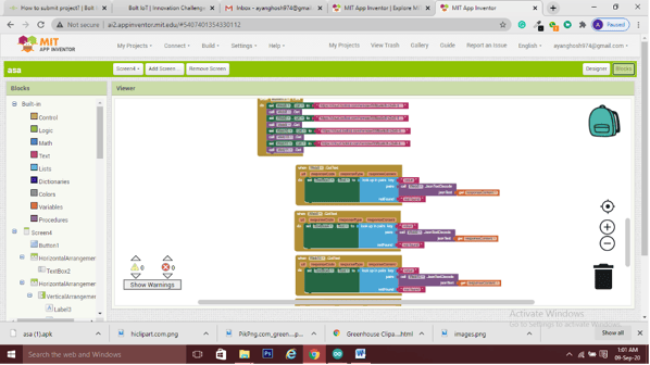
- Now we can see the following console.
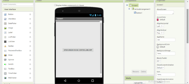
- Now we can make our console as desired from taking the interfaces we want from the left side panel.
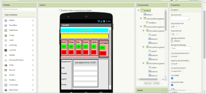
- After making the console as desired it will kind of look like the above picture.
- Then click on the “blocks” on the upper right corner beside “designer”
- Connect the blocks as desired and also to the web, with the URL given the BOLT docs for getting or reading the data of the BOLT.
- After that the blocks will something look like the above picture.
- Now to operate it with the mobile we need to download it to the mobile. [NOTE: the app is only supported on android devices and sadly not in ios devices, so, we will need an android phone to operate the system with this app.]
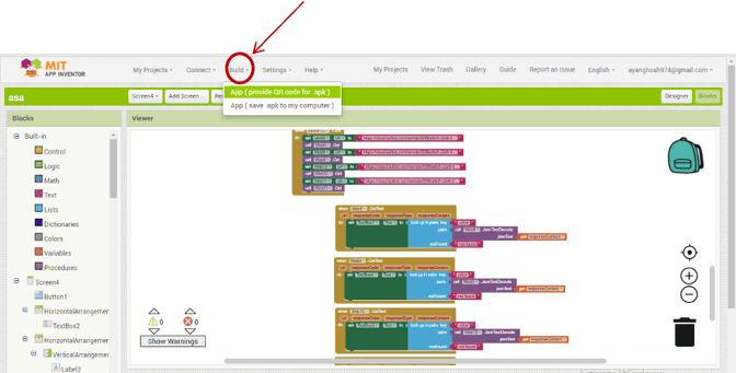
- Now click on the “build” from the tab and then click on the first option.
- We will be getting a QR code in the screen, now we have to scan this code with our android phone and the app will automatically get downloaded in our phone.
- Then we will be ready to use the app for controlling the system
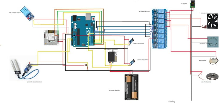
TOTAL WIRING DIAGRAM
CODING
Each and every coding of the project along with the apk file that i had made using mit app inventory, is given in the github link bellow download the project and have a try to make it by your own it is super adventurous.
https://github.com/Ayanghosh-agno/Smart-Iot-greenHouse_Arduino_BoltIot
The Video Demonstration
Watch our project in action (Apologies for the video quality):
Conclusion
After completing with the project i had gain more confidence about the iot and app making field and knowledge about those part want to thank bolt iot for giving me the opportunity to learn and discover the projects by my own, its been a great journey.
Want to build more such IoT and ML projects? Want to learn IoT and ML from basics?
Check out the Bolt IoT and ML training. This online video training is excellent for those who want to start with IoT and ML because it teaches you to build projects from the basics. Click on the button below to know more about the training.