
Water scarcity and water management topics are very closely related to each other. Improper water management leads to water scarcity and vice versa. Don’t assume that this project is also one of the 1000 similar projects based on water management issues.
I am confident that if a person goes through this documentation, he will get to know why this project is unique and smart from other projects! Not only this project solves the old traditional problem of water management in a new way but it also provides a smart way of interacting with robots
Things used in this project
Hardware components-
- Sensors Used With Boltduino/Arduino
- 5V Relay
- I2C LCD
- Boltduino
- 9V Battery
- Bolt Wifi Module
- IRF540 MOSFET
- Water Flow Sensor
- Ultrasonic Sensor X 2
- 1N4007 Rectifier Diode
- 12V DC Solenoid Valve
- Water Lifting Submersible Pump
- 4-way Capacitive Touch Switch Module
- 3-6 V Mini Micro Submersible Water Pump
- LM35 IC (Temperature sensor)
- Sensors Used With Boltduino/Arduino
- Nodemcu
- Piezo Buzzer
- IR Sensor X 2
- DC Motors X 2
- 12V DC Adapter
- TCS3200 Color Sensor
- Capacitive Touch Sensor
- ESP8266 Motor Driver Shield
- Analog Multiplexer IC – CD4051
- Sensors Used With Boltduino/Arduino
-
- Arduino IDE
- Bootstrap Studio
- Spyder (Anaconda)
- Twilio
- Canva
- Hostinger
- Integromat
- Mega Creator
- Pichon (Icons8)
Hardware Setup
Before diving into the Hardware & Software setup, it is important to first understand what the project is intended to do? Way before starting my IoT & Robotics journey I always wanted to solve the problem of overflowing water tanks.
So, after understanding what do Internet of Things & Machine Learning means I thought of making a project which will eliminate this traditional problem to the full extent. But I was startled to see that there were already thousands of projects covering this area. Almost every sensor out there has been used in these projects.
I think all of the projects which were made earlier have the following drawbacks:
- In the real world scenario the water supply chain, from the water source (eg dam, water facility) to water tanks in our home, is a very long one and we have to admit that the problem of water wastage starts from the initial end of the cycle and penetrates through the very last end of that cycle. All of the previous projects only focus on the very last end of the cycle ie the project only deals with the water tanks of our homes.
- The projects were almost passive. By passive I mean that they will monitor the water level and will turn the water motor off when the water reaches a certain level. This whole computation would be done within the microprocessor and the end-user can’t get to know what is happening inside the code at the moment!
- Less interactive projects. If one can provide some motion or life to the immobile projects then it will greatly enhance the chances of implementing the project in real life.
- Very few of the projects use the concept of Machine Learning. Those who use the ML concepts are just using the pre-built easy structured graphs and anomaly detection things which actually don’t make much more sense!!
So, I wanted to make a project which must be very different from the existing projects. Then I came up with the project Wheels 4 Water, a perfect amalgamation of IoT, Machine Learning & Cloud. Let me point the main highlights of my project, which make my project stand out from others.
- Apart from the basic sensors, I have used many different sensors. Be it a water flow sensor, solenoid valve, or an analog multiplexer IC (CD4051), all these sensors helped me to almost nullify the water wastage through the whole water supply chain. In this manner, I focused on the whole water supply chain.
- At every instance of the project execution, the end-user will be updated and informed about each major workflow. The project will talk with the user. Thus making the project active.
- In order to make this project more interactive, I dumped the old idea of integrating IFTTT or using the CLI. Even I have not used either the blynk application or the normal switches in my project. Instead of all this, I have provided four custom options to control the project which include a dedicated website, NodeMCU based robot, customized cloud dashboard & voice control (I have not used any drag and drop feature of Blynk or IFTTT applications)
- Rather than using simple and pre-built ML systems I used the Iterative Dichotomiser 3 algorithm and implemented it via Python so that the robot can actually make decisions on its own after analyzing the dataset.
Functioning of project
One can break down my project into two major parts. One is the immobile Boltduino/Arduino and the mobile NodeMCU based robot. I will discuss the functioning of each of both sections.
Step 1: Boltduino/Arduino
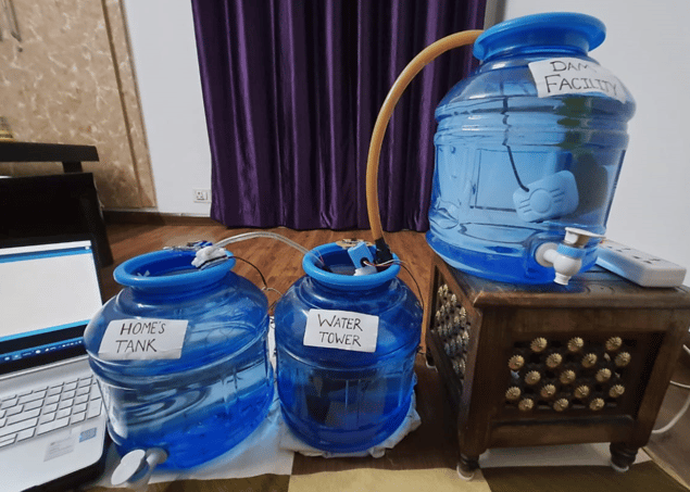
As you can see from the picture that there are 03 water tanks. You can assume the first one to be the main water facility, the second one to be the nearest water tower, and the third one to be the water tanks in homes. The main water facility will get the water from the dam and the water lifting submersible pump will be turned ON and at that point of time, the solenoid valve will be turned LOW. Whenever the water level in the nearest water tower will be less than 20% then the solenoid valve will turn ON and thus the water tower will get filled to a certain threshold (say 95%). When the water tower will be filled then the DC water motor will start pumping out the water from the tower to the water tanks in our home.
At the time of pumping the water flow rate will be calculated through the YS-401 water sensor. Then the total time to fill the water tank will be calculated and accordingly, the instructions will be sent to the robot so that it can reach the destination in time to inform the user.
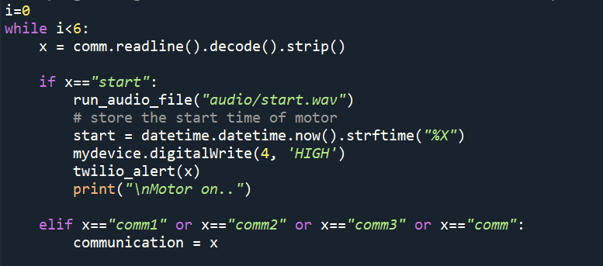
One major aspect of the Arduino setup is that I have to make the Arduino and the python program communicate with each other. I have to do this as Bolt Wifi Module can understand Python language, not Arduino’s language. So I have to make the Arduino pass some certain keywords to the Python program and then the Python program will act accordingly. For this, I used serial communication through the COM port. This was a tricky part as the Arduino has to pass about 6 parameters to the python program and then python program has to proceed accordingly.
In order to make the passed variable understandable to the python code, I used the decode and strip methods. In this case, the decode() method converts the string from UTF-8 encoding to binary encoding. Another problem after using this decoding method was that say for example the passed variable was “stop” then the decode method will append some escape sequences to the variable and now the variable will look like “stop/n/r”. In order to remove the extra escape sequences and also not to affect the binary encoding, I used the strip method as it removes any spaces or specified characters at the start and end of a string. This solved the problem of inter-communication between Arduino and python code.
The python code also comes into the picture here. The python code does the following things:
- Use the ID3 algorithm to predict where the person should be in? For this evaluation, I have made the following custom dataset:
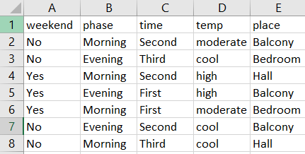
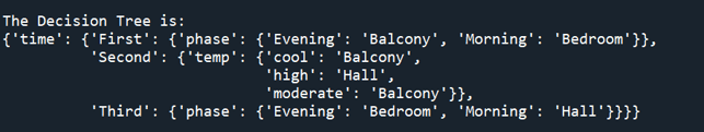
In the dataset, the robot has to predict the place attribute while the other 04 parameters will be computed automatically through the python code. The snippet showing the decision tree made by the python code using the ID3 algorithm is as follows:
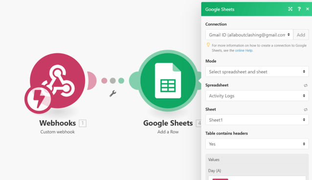
After evaluating the place, the same is uploaded to a google sheet so that the user can have a log of the time periods and all other details about the water tank. The Integromat scenario for uploading all the attributes’ values to the google sheet is as follows:
A couple of more scenarios are there ie for fetching the data and also uploading the predicted values to the google sheet.
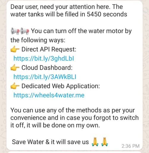
2. To make the project more active, I have used Twilio’s API to send Whatsapp updates for every major workflow.
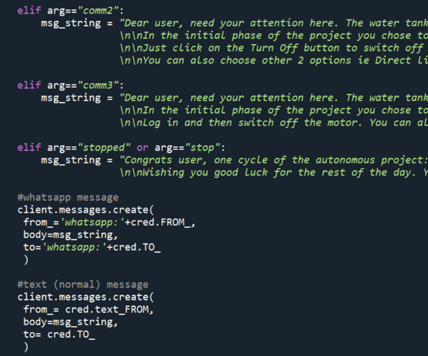
A total of 04 Whatsapp updates will be posted on the user’s registered number. But what if there is no Internet connectivity with the user? Then, in this case, 04 normal text SMS will be also sent which makes the project more relatable to the real world. Following is one of the snippet of the updates:
Before moving further I would like to present the sketch of the hardware connections for the static Arduino section. Here it is:
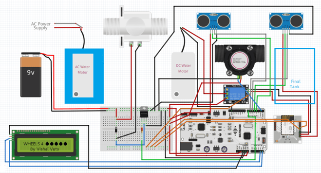
I just want to tell you that the I2C LCD will be updated several times during the course of the project. Be it updating and printing the predicted value or displaying the total time to fill, one can easily keep a track of important parameters through the LCD.
There could be many possibilities in which the user may not be able to turn the motor off. In those scenarios, the Arduino will use the TTF (Time To Fill) to turn off the motor, when the TTF is about to be reached. So, in this way, the project becomes quite interactive and the user also gets timely updates regarding the whole project.
The user will also hear voice outputs from the computer so that he/she can have a track of where the execution is at the moment? One of the sample audio files is as follows:
As earlier I told you that the python program and Arduino code will communicate via serial communication. According to the project, the Arduino code will have to convey 6 variables to the python code so that the Bolt Wifi module can work accordingly. Those 6 variables are as follows:
| Variable Name | Purpose |
| start | Turning the water motor on when the nearest water tower is full |
| time to fill | By YS-401 water sensor, calculate the time needed to fill the water tank. Has to be reflected on the LCD screen |
| robot/noRobot | If the robot will take more time to reach the place than the ttf, the robot should not be deployed which is conveyed by the noRobot variable. If this is not the case then robot variable is transferred |
| stop/stopped | After reaching the place, did the user press the touch sensor or use any of the 4 mediums to turn the motor off. If he did that then the variable will be set to stop and if the user for any reason did not turn it off the variable stop will be sent so that the autonomous execution can proceed |
| true/false | If the robot has gone for the destination and still not reached the final place due to some obstruction then the prediction variable will be set to false & if it reaches the final place then it will be set to true |
| comm /comm1 /comm2/comm3 | Passing the variable through which the program will get to know that the user has chosen which option out of the 4 to turn the motor off. So, that at the end of execution there is clarity for the program |
From the above video, now you must have understood why the 06 variables play a much important role with the static Arduino and computer. As the video was just for the demonstration purpose the variables were transferred in a few seconds but in the actual project’s working this will not happen.
- NodeMCU based robot
The first work for the robot is to fetch the place attribute so that it can find the place where it has to go. Once the robot fetches that value then the TCS3200 color sensor comes into the picture. Basically in the dataset, there are 03 values for place attribute which are balcony, bedroom, and hall. From the starting point of the robot to the final destination I had laid down 03 different colored lines so that the color sensor will follow a particular colored line after getting the predicted value. The place has the following colors:
- Red – Bedroom
- Blue – Balcony
- Green – Hall
So, the robot will find the path through the custom-made direction functions. When the robot will reach to the end then it will wait for 20 seconds and then it will check whether the user clicked on the capacitive touch sensor. If yes, then the NodeMCU will send an API request to the Bolt WiFi cloud and in this manner, the water motor will be switched off in time.
The sketch for the hardware connections for the mobile robot is as follows:
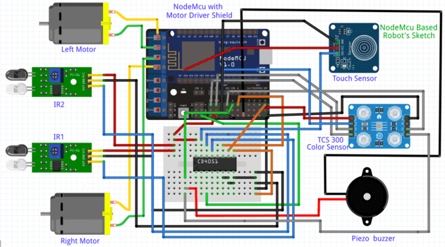
In the hardware configurations, there were two most challenging and tough parts. These were using the ESP8266 motor driver shield & using the multiplexer IC with the motor driver shield.
Using the ESP8266 motor shield was difficult because in the shield’s official datasheet nothing is clearly explained. But after several repeated attempts I sorted the overall functioning of the shield. NodeMCU is placed on the top of the shield so that both become one in the other. A total of 2 DC motors can be connected so that is why I used a 02 wheeled robot which was controlled through the DC motors while the Caster wheel provides the stability to the overall chassis. As I used 02 12V DC motors I have to either use a 12V DC cell combination or can use a 12V DC power adapter to power up the motors. The major drawback of using the 12V cell combination was that the cells get discharged very quickly so this option doesn’t seem viable at that moment. That’s why I turned up for the 12V DC adapter solution as it seamlessly provides enough power to the motor shield and motors. Do note that I have short-circuited the Vin and Vm pins of the motor shield so that the power coming from the motors can also be utilized for powering up NodeMCU.
Using the multiplexer IC with the motor driver shield was also quite a bit of a challenge as the CD4051 multiplexer IC is basically a 03 select line-based (S0, S1, and S2) multiplexer. This means that we can insert 23 = 8 analog sensors with this IC and use the single port ie A0 of the NodeMCU to read all 8 values. But in my case, I used only 2 IR sensors which means I don’t know what I have to do with the third select pins? In many attempts, the third select line was giving random values which were not even needed. After some trials, I got to know that the third select line must be provided a voltage of 0 so that the pin should not float.
Software Programming
Step 1:
I have almost discussed the difficult tasks of the code up in the above sections. But I want to make it clear that the overall code of this project spans over 2000 lines (excluding the whitespaces). So, I will be providing a brief of each of the files which I have used in this project.
Just for your convenience, I am laying out a table that tells the working of each file:
| robot.ino | Catch the users’ input & reach the predicted place |
| arduino.ino | Serial comm with python & data collection |
The above-listed Arduino files are for Arduino and NodeMCU respectively. The below-listed files are python files that do the manipulation with the dataset and then upload/fetch the same via Integromat.
| attribute.py | Gathers values for the data points to be pushed in ID3 algorithm |
| credentials.py | Stores API keys, SSIDs, authentication variables |
| integromat.py | Retrieval of information from Integromat’s scenarios |
| prediction.py | Collect the attributes and uses the ML algorithm to predict the place |
| project.py | Main file which ensures smooth functioning of the project |
The best understanding of the code will be through the working video of the project. So, do look at the working video of the project at the end of this documentation.
I have explained the hardware connections, defined most of the working of the code, and also shared the code in this documentation. Only the conclusion must be remaining. No, guys as in the introductory part of this documentation I told you that I have made a dedicated website to control the water motor. I know if you had gone through every paragraph of this documentation till now then your expectations must be very high and I am pretty confident that after going through the dedicated website section you will be impressed 😁
Step 2: Website Programming
For the front-end part of this website, I have used CSS, Bootstrap. Just to speed up the process I used Bootstrap Studio so that I can make the static website in a quick span of time. But the static website was not fulfilling the main purpose of this project. How can a user use a static website to interact with the cloud?
So, in order to turn this into a fully functional dynamic website I added a lot of transitions, JavaScript and also added the back-end (database functionality). After doing so the user can easily interact and thus login into his account whenever needed. For integrating the website into the database I used PHP language so that I can execute the required SQL commands whenever needed (or according to the users’ input).
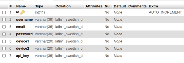
The SQL database is named wheels4water and inside it, there are 2 tables which are users & vacation_logs. Users table stores the information related to the user whereas the vacation_logs store the information related to the scheduling of a particular account.
The structures for users table is as follows:

The structure for vacation_logs is as follows:
And as I already discussed in the video that the customized email templates, which are sent to every user at the time of signing up or adding a new device, add a visual treat for everyone. The website apart from being visually appealing and responsive allows the user to keep an eye on the project anytime and anywhere. The scheduling section adds more dynamic behaviour to the site and the icon glow section perfectly sums up the hard work I put into this project.
All of you must be thinking that at the starting I wrote that there are 4 ways of controlling the water motor but till now I only described NodeMCU based robot, voice command option, and website option. Where is the fourth one ie Cloud Dashboard?
Step 3: Cloud Dashboard
I have used Bolt’s WiFi Module to turn on and off the water motor through the relay. The main reason for choosing this module to turn on and off the water motor was because through Bolt’s Cloud Dashboard I can easily plot a graph that must be showing the time for which the water motor was turned on/off.
You can find the basic steps to create a product in Bolt Cloud by clicking here. As far as my product is concerned I have to make a dashboard such that through which user can control the motor. For that, I have to place a button on the pre-formatted UI and I assure you that it’s hard to tweak a UI whose HTML structure you don’t know. But there came JS to my rescue. I dynamically add some code in the product code section to make a button live and thus users can interact with this one to turn off the water motor.
The code for the customized product is as follows:
setChartLibrary('google-chart');
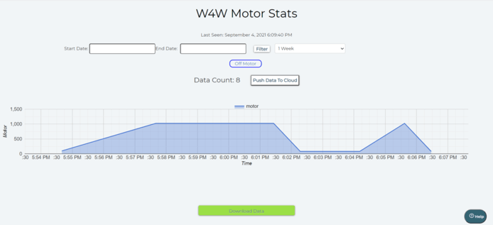
setChartTitle('W4W Motor Stats');
setChartType('areaGraph');
setAxisName('Time','Motor');
plotChart('time_stamp','motor');
let anchor = document.createElement("a");
anchor.innerHTML = "Off Motor";
anchor.href = "https://cloud.boltiot.com/remote/e719e4f0-cc5d-427b-a0aa-6b9d1ceb0f28/digitalWrite?pin=0&state=LOW&deviceName=BOLT8024008";
anchor.target = "_blank";
anchor.style = "display: block; width: 100px; text-align: center; margin-top: 20px; margin-left: 450px;border-radius: 10px; border: 2px solid #0000FF";
document.getElementById('drop').appendChild(anchor);
Okay, now I am equipped with a button on the dashboard which can be used by the users. I have also written the necessary lines of code to use the google chart but wait how am I going to plot/extract the time period for which the motor was on/off? For turning on and off the motor I have used the digitalWrite function on pin ‘0’. But we can plot the graph for only analog values gathered through the A0 port of the Wifi module.
To understand the solution for this problem let’s start from the initial step ie creating the product on the cloud. For my product, I opted input device & GPIO commands during the product creation phase. Secondly, in the Hardware section of the product, I assigned pin A0 the name motor. As I have used a relay to connect the bolt wifi module and Arduino so I connected the Vin pin of the relay to the breadboard and from that breadboard’s pin I also connected the A0 pin of wifi module. So, in this manner, the AO pin’s value increases from 0 and thus in the dashboard, a graph was formed which will drop down to 0 if the motor is off and whenever the motor is on then the graph climbs up.
Now as I have explained everything to you I am sharing the screenshot of the same so that you can have a brief idea about what I was telling.
Demo
Till now I have explained each and every concept of this project. In the documentation, it all looks great but does it even work? Let’s check it out 👇
I think this video must have cleared all of your doubts as it perfectly tells us how the NodeMCU based robot, Arduino, and computer are communicating with each other to bring out a project which literally is unique and solves the issue of water management to the fullest.
Conclusion
1. As already mentioned I will be creating 4 custom options for the project and I did that. I had created the website, incorporated the capacitive touch sensor, automated the voice control thing, and created the cloud dashboard.
2. This is a project which can be deployed in the market as it is almost optimized. It is also cost-efficient as the whole hardware setup costs around $130. As in the real world, the magnitude of the sensors will be increased, so that the cost will only reach up to $300 (which is a quite remarkable feat).
Therefore, I magnificently solved an old-age problem of water management by incorporating about 30 electrical components together and making a project which can be either used by a single person or by the entire community.
Want to build more such IoT and ML projects? Want to learn IoT and ML from basics?
Check out the Bolt IoT and ML training. This online video training is excellent for those who want to start with IoT and ML because it teaches you to build projects from the basics. Click on the button below to know more about the training.